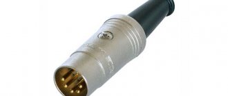
Hi all. I’ll start keeping my logbook of the submitted article, because... all my subsequent topics will refer to it in one way or another. I installed a bunch of things on my car. And while installing additional wiring on my car, I encountered a big problem, namely, the inability to purchase ready-made shielded wires needed (for example, with a cross-section of 0.85 mm2 and the number of 4 or more pieces in one screen). Well, someone will say, yes, you can take a USB or interconnect cable and make the one you need from them - I DO NOT agree. The cores of the USB cable have in some cases an insufficient cross-sectional area (0.3 mm2 maximum) and are only suitable for transmitting audio and video via digital (rear view mirror with a parking screen or transmitting sound between the MMSS and the amplifier and between the amplifier and the ceiling via a DIN cable) . And the interconnects are so huge and take up so much space that when using them, it becomes impossible to reinstall the decorative plastic of the interior in its original place or to wire them in narrow spaces behind the front instrument panel (dashboard). I didn’t find the necessary shielded cables on the Ukrainian market (I don’t know about Russia or other countries). Who found it and where, share it in the comments. Therefore, I made all the necessary shielded cables myself. As practice has shown, the result exceeded all expectations. Below is my version of the “production” of a shielded cable. To create, you need the following components: 1. Aluminum tape. Moreover, it is VERY important that the composition (written on the label) contains ALUMINUM. Adhesive tapes of the type “for gluing aluminum/silver surfaces of your car” are not suitable - they only contain plastic painted in aluminum color. You can buy it at a construction supermarket 100%. If you are not sure about the conductivity of the tape, take a resistance tester with you and test it locally.
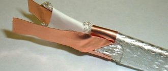
Next, we take the required number of wires, add a wire free from insulation to them and connect them into a braid. After this, we slowly wrap the wires with aluminum tape, with the conductive side facing in and the adhesive side facing out. This will enable the wire free from insulation to become an active screen and ensure continuous conductivity of all sections of the screen from one plug to another, because You are unlikely to be able to continuously apply the screen (adhesive tape). It will also ensure a tight fit of the screen with the adhesive side to the future insulation after shrink procedures. It will look something like this:
That's all, I hope it helps everyone.
How to make a shielded cable for a crankshaft sensor or a knock sensor? We do not consider the question “why shield.” Read relevant literature.
1. Buy ready-made, thermo-oil-gasoline resistant. For example, MGTFE is an excellent cable of the highest quality.
2. Braid the wires.
3. Foil. This solution has been personally tested and works on multiple machines. I have also seen a crankshaft or knock sensor foil wire in the stock wiring of one of the modern cars. I think it was a Mitsubishi.
Any foil is needed. I found regular food in the kitchen. You can also use aluminum tape (not aluminized shiny film, but real aluminum)
We tear off the foil in strips and carefully wrap the wires
Place the next piece with an overlap of several centimeters
We clear the wire to a length of 5-10 cm and spread out the copper wires. This will be the shield ground wire. Grounding is connected only on one side of the cable. That's what cable science says.
Here in the photo the copper wire is not tinned. This is a mistake; the wire needs to be tinned to prevent the creation of a galvanic copper-aluminum pair, which will destroy the connection.
We wrap the spreader mixed with layers of foil into the last centimeters of shielding.
We wrap our cable with electrical tape
Don't forget to connect the ground wire to ground.
Isolation of wires from interference: shielding
Electromagnetic interference (EMI) is an external or internal electromagnetic phenomenon that can have a negative impact on the quality of operation of technical equipment (TE).
Vehicles are subject to certain requirements regarding both their noise immunity and noise emissions. Read about the quality criteria for the functioning of a technical device and EMC testing in the article “EMC testing”.
Currently, against the backdrop of constant consolidation (growth) of electronic components and an increase in the speed of signal processing, failures of devices and systems often occur due to electromagnetic influences.
Isolating wires from interference: types of EMI
Let's consider the issue of shielding the cable (wires) as part of the functioning of servo systems. If the wires are not insulated from interference, the stability of these systems is disrupted, which leads to signal transmission errors and sometimes switching devices on/off. The electromagnetic interference itself can propagate through the cable or be emitted by the cable itself. The range of the former is usually up to 30 MHz, while the latter (radiative) is over 30 MHz.
Types of EMF
You need to start understanding the principles of shielding by understanding the principles of EMF transmission through connections. This is necessary because wire shielding that is effective for some types of connections may be completely ineffective for other types. Moreover, if the shield is not properly connected (grounded), you can get even worse results than without shielding.
Four types of interference can degrade signal quality in circuits:
- capacitive;
- inductive (magnetic);
- internal;
- radiative.
Capacitive interference. On the one hand, such interference is among the most easily suppressed, and therefore causes fewer problems. On the other hand, such interference may result in distortion of RF signals in conductors with high output resistance. To suppress this type of interference, wires with grounded shielding should be used.
Inductive interference. The cause of this type of electromagnetic interference is the influence of a strong magnetic field, which operates on the principle of a generator. This can cause a relatively low impedance current to flow through the conductor, which can disrupt signal transmission. These interferences, as well as the consequences of their impact, can be quite powerful to disable/enable technical equipment. An effective way to suppress inductive noise is to use twisted pair cables that have a grounded braided shield. Shielding wires with foil is not as effective due to magnetic eddy currents.
Read more about this type of interference in the article “Inductive interference”.
Internal interference. Such interference includes EMI, which occurs when the source is directly connected to the system. For example, when the power supply creates impulse noise on the AC line. Methods for suppressing internal noise include isolation, filtering, or other impedance matching techniques. When suppressed, shielding is ineffective, but it can be used to prevent interference from leaving the system. For strong internal impulse noise in an unshielded system, it is possible for it to become inductive.
Radiative interference. This type of interference is the most complex and has a number of limitations related to frequencies. To suppress such interference, shielding the wires with foil is not enough. Braided shielding can be effective, although there are additional requirements for its use in this case. These include, for example, the following:
- the screen inside the shielded wires must not be interrupted;
- screening must be complete, from all directions, etc.
Use of metal mesh for shielding
Figure 1. Metal braid When installing various radio-electronic and electrical devices, it is important to pay attention to the problem of their noise immunity. Incorrect selection of the connection diagram, unsuccessful method of cable routing, incorrect grounding and shielding scheme - all this can lead to malfunctions and even complete failure of the devices. Typically, to eliminate the influence of extraneous electromagnetic fields on devices, electrical mechanisms and equipment when performing installation work or connecting to power networks, as well as laying cable lines, a shielded cable is used.
Methods for getting out of this situation
To solve the problem, it is not necessary to completely replace the cables; it is enough to arrange additional shielding, which will significantly reduce the influence of electromagnetic fields. Structurally, it can be done in the following ways:
• installing an enclosing metal screen;
• spray conductive materials onto the inner surface of the equipment body.
However, there are designs and situations where the use of such screens is impossible or impractical. In this case, you can do the shielding yourself, thus localizing the source of electromagnetic interference. The essence of shielding is the limitation in space of electromagnetic energy that is generated by the field source. Very often in electrical appliances, protection from the mutual influence of wires and cables is carried out using a screen in the form of a braid of copper wires or a winding with metallized foil. These screens are divided into 2 types:
• magnetostatic;
• electromagnetic.
The most optimal method for properly shielding wires with your own hands is to use metal shielding mesh, which reduces the energy of electromagnetic waves by reflecting energy or absorbing energy by a conductive medium. The material from which it is made must provide the maximum possible protection and reduce interference generated by the electromagnetic field. The type of material in this case is selected depending on the nature of the interference field - magnetic or electrical.
Metal braiding and its types
However, there are designs and situations where the use of such screens is impossible or impractical. In this case, a metal braid is used (shielding braid). It reduces the energy of electromagnetic waves by reflecting energy or absorbing energy by a conductive medium. The material from which it is made must provide the maximum possible protection and reduce interference generated by the electromagnetic field. The type of material in this case is selected depending on the nature of the interference field - magnetic or electrical.
Shielding braid - brands and materials
Depending on the nature of the interference and the operating conditions of the cable, the metal shielding braid for the cable is available in various designs. Some of them:
• PML copper braiding, tinned with POS-40 tin-lead solder for temperate climates (PML UZ) and tin for tropical climates (PML T2);
• PMLOO made of copper wire tinned with tin;
• PMVLOS made of copper, silver-plated wire;
• PMLON made of nickel-plated copper wire;
• PBAMO made of bimetallic Al-Cu (aluminum-copper) wire coated with tin;
• PBAMS made of Al-Cu (aluminum-copper) bimetallic wire coated with silver;
• PBAMN made of Al-Cu (aluminum-copper) bimetallic wire with nickel coating.
When using braided cables, please note that:
• such protection requires more space in the housing compared to conventional wires;
• the braid must be connected to the body to create a shielding effect;
• installation of shielded wires is more difficult than unprotected ones.
PML braid and PSO braid
Tinned copper braiding PML is used for shielding wires and cables to prevent the negative influence of electromagnetic interference on the operation of various devices used in the national economy. Wires can also be used to ground various types of devices. The braid has the following dimensions:
| Braid sizes | Smallest diameter of the shielded (armored) product, mm | The largest diameter of the shielded (armored) product, mm |
| 3x6 | 3 | 6 |
| 6x10 | 6 | 10 |
| 10x16 | 10 | 16 |
| 16x24 | 16 | 24 |
| 24x30 | 24 | 30 |
| 30x40 | 30 | 40 |
| 40x55 | 40 | 55 |
Isolating wires from interference: types of shielding
There are three types of cable shielding:
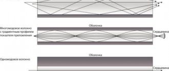
Shielding wires with braid. This type of wire insulation against interference consists of copper threads woven into a network. These threads can cover both individual conductors and twisted pairs, and simultaneously all the cores in the cable. The percentage of coverage is determined by the density of the copper threads in the braid: the higher it is, the better the protection against EMF and the lower the radio emission. The flexibility of such a braid, as well as its service life, is directly affected by the diameter of the threads.
Shielding of wires with a spiral winding. This type of shielding provides greater flexibility and bending life than with braid. A spiral winding is a bare or tinned wire that is twisted in a spiral around a conductor. This type of braid is most effective for low frequencies, coverage is more than 95%. Spiral winding as shielding is used in the most flexible cables that are resistant to deformation (twisting, etc.). In such cables, other types of shielding (braid and foil) can be damaged during the cable twisting process.
Shielding wires with foil. This is usually aluminum foil on a polyester backing. This substrate provides mechanical strength. Aluminum provides effective protection against capacitive-type RFI.
Methods for applying a foil screen to a conductor:
- foil to the conductor;
- foil out;
- with the edges of the wound strip of foil being folded into a Z shape.
How to shield a cable
It is almost impossible to make a protective screen for a cable on your own; moreover, it is better not to do this without experience or at least specialized education. It is better to trust factory cable wires, of which there are a huge number in stores. The protection is placed under the main sheath of the wire. Self-cladding of the wire requires care and precision so that the fabric remains intact and without damage.
Cable with screen
Typically, wires are shielded using two types of materials: either a braid or a solid foil covering is created. Foil has its pros and cons. Simply put, it is a thin layer of aluminum. Using the wire braiding method, a high level of grounding is ensured. It is considered one of the most reliable methods, but the disadvantage is that minimal gaps may form in the surface. Their size depends on the thickness and length of the wire.
Subscribe to the newsletter
Quite often, at industrial facilities, in production workshops, office buildings, etc., there is a need to jointly lay cables for various purposes in one trench, tray, cable channel, etc. The insulation of current-carrying conductors and the cable sheath do not provide effective protection against electrical noise and parasitic electromagnetic radiation arising due to currents flowing through the cable and negatively affecting the operation of the equipment. For such installation conditions, a cable with shielded cores will be required.
Recommendations
Comments 59
Instead of electrical tape, you can use heat shrink.
A cable like this costs 20 rubles per meter
Sorry for my ignorance, but why a shielded cable for DPKV? What are the advantages of it?
Usually it is necessary for dpkv and dd for protection against interference
I guessed this myself, that the screen is anti-interference, but what kind of interference can affect the DPKV? And how can they influence?
A car has almost the worst conditions for electronics in terms of the level of interference and interference. Well, for example, the ECU will begin to see detonation where there is none, and make mistakes in counting the pulley teeth
Shielded cable diagram
The properties of a shielded cable directly depend on its intended purpose, therefore the design of cables of different types differs from each other. For power cables with a rated voltage of up to 3 kV, a screen is usually applied to the twisted conductors using a common screen made of foil material or braided copper wire, and for data cables, in addition to the general screen, individual pairs can be protected from the effects of electromagnetic fields. The marking of shielded cables differs from other types of cable by the presence of the letter “E” in the letter abbreviation. However, for power cables with voltages above 6 kV, the presence of a screen in the design is mandatory, therefore the letter “E” may not be included in the designation of a screened cable.
Types of Shielded Cables
According to its purpose, a shielded cable with copper or aluminum conductors can be:
• power, designed for alternating voltage up to 220 kV with a frequency of up to 50 Hz. Depending on the voltage, the screen can be applied directly to the conductors or after they are insulated. • control, used to transmit signals from various sensors to measuring instruments. In this case, the use of a shielded cable is required to protect the transmitted signals from external electromagnetic interference. • combined, consisting of power and control cables enclosed in one sheath. A shielded cable of this type is usually produced in rubber insulation and is used to control and connect various mobile mechanisms to power networks. The screen serves to protect control signals from interference created by supply conductors transmitting alternating voltage up to 10 kV. • signal-blocking, designed for installation in conditions requiring increased protection from the effects of external electromagnetic radiation. Widely used in security and fire alarm systems. • information transmission, used in digital telephone communications and computer communications. Like all other types of cable products, shielded cable for structured communication systems is available for external and internal installation.
is one of the leaders in the sale of cable products and has warehouses located in almost all regions of the Russian Federation. After consulting with the company’s specialists, you can purchase the brand of shielded cable you need at competitive prices.
Shielding of electrical wires
Shielding wires solves 2 problems:
•reduction of interference on wires extending beyond the controlled area from electromagnetic radiation of main and auxiliary technical means and systems;
•reducing the level of electromagnetic radiation from information line wires of main and auxiliary technical means and systems.
The physical basis of shielding in order to reduce parasitic interference on wires is discussed in the previous paragraph. This subsection discusses the physics of shielding cable wires.
Shielding the wire of an asymmetrical cable is done by placing it in a screen - a metal (iron, copper, zinc, lead) pipe and a metal mesh braid (braid). To shield the electrical component, the screen is grounded (Fig. 12.3).
Rice. 12.3.
Electrical shielding of unbalanced cable
The charges in the wire create an electric field, the lines of force of which attract the charges to the inner surface of the screen. The resulting charges on the outer surface of the screen are neutralized by earth charges. The electric field outside the screen is determined by the small value of the secondary electric field caused by incompletely compensated charges on the outer surface of the screen due to the finite, non-0, resistance of the grounding circuits and the screen (from the grounding point to the measurement point). The more grounding points (multipoint grounding), the lower the electrical resistance of the screen and ground electrode, the lower the secondary electric current intensity. But, as a rule, only the ends of the cable shield are grounded when connecting it to the connectors of radio-electronic equipment. Therefore, the strength of the secondary electric field increases towards the middle of such a cable and decreases towards the ends.
The sources of spurious magnetic field radiation are two magnetic frames. The first is formed by a circuit - a wire and a screen, along which, in accordance with Fig. 12.3 a current of 1 e flows. The circuit of the second frame is formed by the same wire and the conductive surface of the earth, through which current I Ш
It is obvious that 1ob = 1e + 1z = 1p. The radiation power of the frames depends on their area and flowing currents. The influence of the screen on reducing the reverse current in the ground is taken into account using the current screening coefficients K, equal to the ratio of the value of the reverse current in the ground 13 to the total value of the reverse current 1rev. For j shielding method in Fig. 12.3 in the audio frequency range kt ~ 0.05. In most cases, the distance from the wire to the screen a is significantly less than the distance h from the wire to the ground. Therefore, 1 the area of the second frame is significantly larger than the area of the first. Although 1 current 1е > 1з due to the higher conductivity of the shield than the ground, noi at h » and the spurious radiation of the wire-ground frame is not-I permissibly large. To reduce it, it is necessary to reduce h and the current 1c. Current 1z is provided in the absence of grounding of the screen at load I (Fig. 12.4).
Rice. 12.4.
Unbalanced cable shielding
But at the same time, due to the increase in grounding resistance, the secondary electric field created by the screen increases. Therefore, in practice, the grounding option is chosen based on minimizing the total spurious radiation of the electric and magnetic components of the electromagnetic field. For example, if the current 1p contains a direct component, then it is advisable to ground the screen at the load through a low-frequency filter, for example through an inductance that has a low resistance for direct current and a large one for alternating current (Fig. 12.4). This provides effective electrical shielding at low frequencies and magnetic shielding at high frequencies at which the second frame can generate significant radiation.
Shielding the wires of symmetrical cables in order to reduce radiation caused by the asymmetry of the wires relative to another conductive surface or ground is carried out similarly to the methods discussed.
The greatest shielding effect is achieved when using metal water-gas pipes, the sufficiently large thickness of the walls of which provides a large weakening of the magnetic field at low frequencies. It is more convenient to lay cables in a lead sheath, since they ensure that the cable can be bent anywhere along the route. These cables provide high resistance against aggressive environments and effective electrical shielding. Since lead is diamagnetic (with (I < 1), magnetic shielding is achieved at high frequencies, at which the greatest shielding effect is achieved due to eddy currents. Even greater Screens in the form of a braided mesh that allows multiple bends have elasticity. The braid covers 60-90% of the surface of the insulated wire. But the presence of holes in the braid worsens the magnetic shielding compared to a solid screen by 5-30 dB.
If shielding the wires of asymmetrical cables is the most effective way to significantly reduce their spurious electromagnetic radiation, then for symmetrical cables there are other and cheaper methods. They provide measures to ensure more complete compensation of the fields created by currents of the opposite direction in the wires (cores) of a symmetrical cable.
Field compensation
Low-frequency and high-frequency fields created by currents in symmetrical cables have almost equal strengths and almost opposite phases. Stray emissions from the wires of symmetrical cables are caused by different distances of the wires from the point in space at which the radiation level is measured, and different values of the capacitances between the wires
us and the conductive surfaces in question, including the ground. This difference is caused by the different arrangement of wires in space, design differences and heterogeneity of the material of the wires and their insulation.
Compensation of the fields of the wires of a symmetrical cable when it is laid parallel to other cables is improved by balancing the wires using additional capacitors or by placing the cores in a multi-core cable or bundle in such a way as to reduce their influence on each other. To do this, measure the capacitances between the wires and install additional capacitors Сс to achieve equality of capacitances between the wires in question (Fig. 12.5a)).
Rice. 12.5.
Balancing cable wires More convenient for balancing cables are the so-called differential capacitors of variable capacitance SDS. (Fig. 12.5). By rotating the adjusting screw of such a con-; The densator achieves the minimum level of the field strength indicator of the measuring device installed in the controlled location. The connection of balun capacitors is made in special balun couplings, which are included in the cable break (for long cables) or in the connecting connectors.
In the industrial production of multi-core cables, the arrangement of the cores of one group is provided at the same distance from the cores of another group. This circumstance is important to consider when installing the cable. For each circuit, cores are selected that are located at an equal distance from the cores of other circuits.
To compensate for the fields caused by different distances of the wires from a point in space, the cable wires are twisted. A cable consisting of two twisted wires is called twisted pair or bifilar. Increasing the compensation of the fields of different wires of a pair is achieved by the fact that the field at the considered point in space is a superposition of the fields not of two parallel wires with different distances from the measurement point, but of the fields from sections of wires with a length corresponding to the twisting pitch. Since after each twist the location of the wire sections relative to the measurement point changes to the opposite (the closer section of the wire becomes more distant), then significantly more complete compensation of the fields from wires with the opposite direction of current occurs. It is not possible to achieve complete field compensation, but with a sufficiently small twist pitch, the radiation attenuation reaches practical values that are not noticeably inferior to more expensive shielding. For example, when the twist pitch is reduced by 3 times (from 55 to 18 mm), the emissivity decreases by approximately 30 dB. The absolute value of attenuation of twisted pair radiation with a step of about 2 mm reaches 80 dB. The low emissivity, lower cost and greater flexibility of twisted pair contribute to its widespread use as a cable for local computer networks located inside the same building.
Currently, unshielded cables with twisted pairs made of copper wire (UTP - Unshielded Twisted Pair) and shielded cables with twisted pairs of copper wire (STR - Schilded Twisted Pair) are used. STR cables of the 3rd, 4th, and 5th categories are most often used. Cables of the 3rd category provide transmission speeds of up to 10 Mbit/s, 4th category - up to 25 Mbit/s, 5th category - up to 155 Mbit/s.
I To increase radiation attenuation, the twisted pair is placed in a shield. Shielded twisted pair cable is effective at frequencies up to 100 kHz, but losses increase significantly at frequencies above 1 MHz. As a shielded twisted pair, a twist of three wires (trifilar) is also used, two of which transmit signals, and the third is grounded. The efficiency of shielded cable can be more than 100 dB.
The concept of speaker cable
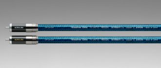
Shielded speaker wires
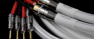
Before moving on to the main topic, let's take a closer look at the topic of speaker cable. Today, customers are offered a sea of assortment, the choice of which is not so easy. In any case, you must proceed on the basis of your own budget, taking into account information and knowledge about the types of cable. “Average,” so to speak, motorists, as a rule, don’t bother too much with wiring. They think that there is not much difference, but they are deeply mistaken.
Note. Naturally, if the owner of a budget acoustics system with simple speakers thinks so, then there are no questions. But the owner of an expensive speaker system, on which, as they say, no expense was spared, is obliged to pay attention to the speaker wires, since a considerable percentage of high-quality music reproduction depends on them.
Shielded acoustic wires
The following is important information about the speaker cable:
- Without going too much into the jungle of physical and technical details, let us note one obvious pattern. It concerns sound distortion, which is less, the better the quality of the speaker cable;
- Resistance is considered a decisive value, a parameter of any cable that determines its quality. So, the lower this resistance, the better for the transmitted signal.
Note. In turn, the resistance is directly affected by the material from which the cable is made. In addition, the diameter and length of the wiring are equally important.
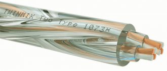
- If we proceed from the opinion that an acoustic cable consists of two metal conductors isolated from each other, then today the most popular is copper wiring, which consists of 20 conductors;
- As for the diameter of the wire or its cross-section, the standard size is 2-4 square meters. mm is considered popular. For example, the signal transmission speed in such a cable, provided that the length is appropriate, is approximately equal to the speed of light.
Wires for acoustics
Note. The ideal wiring resistance is zero when the cable length is 3 meters and the cross-section is 2.5 square meters. mm.
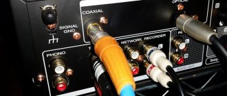
- All interconnect cables are called shielded (see Shielded acoustic cable: how to choose). In this case, the screen is a kind of protection of the conductor from EM interference. It is more correct to call protection in a particular case an external screen, which can be made of different materials: metal, plastic, etc. The type of protection also varies: braiding, foil, etc.
Note. It is believed that such a shielded cable, which requires a mandatory connection to ground (to protect against interference), is not ideal.
Acoustic shielded wire
- For this very reason, the balanced cable was invented. So, in an unbalanced cable there is one internal rod responsible for the main signal. As for the external screen, it is doubled due to the returned path signal;
- A balanced cable already implies the presence of 2 conductors, called hot and cold. Both outputs carry the same signal, but the difference is determined by their similarity. The effectiveness of such wiring is determined precisely by the balance of both conductors;
- In addition to balanced and unbalanced cables, another type of wire is known, called Star Quad. It is specially designed to improve interference immunity. This wire operates with 2 pairs of internal cables that are connected in parallel (of course, they are insulated).
Shielded cables or EC are rightfully considered the best and most versatile, as they are equally suitable for both domestic and professional needs.
Note. Among other types of interconnect cable, one can distinguish a conductive wire in which the protection is made in the form of a plastic screen. In such a cable, a copper wire runs along the entire screen. An ideal option for short distances, that is, in car audio. On the contrary, when it is long, its effectiveness is lost.
There is also a microphone cable type. It is very sensitive and protected by a woven screen. This type of cable was developed specifically for working with a microphone. Provides low noise during use. Finally, foil cables are rigid and do not like sharp turns and bends. But such wiring provides excellent properties.
How to shield a wire with your own hands - Metalworker's Guide
05/16/2000 David Galperovich
But careful analysis shows that this answer is ambiguous.
From external interference or from transient interference inside the cable? How does it protect the screen from interference emitted by the cable itself? Are there other effective and inexpensive anti-interference techniques? How are cable parameters related to the presence of a screen? We will consider some of the questions raised.
Some cabling standards support shielded cables, while others provide them as an alternative to unshielded cables. The most general recommendation is this: first get the most out of unshielded cables, and if this turns out to be insufficient, then use more expensive and complex shielded systems.
There are two known stages of cable interference protection:
A.
symmetry and selection of twisting steps;
b.
shielding, external and internal.
Symmetry
In a twisted (twisted) pair, the wires are swapped - this achieves symmetrical conditions for excitation of interference in the wires of the pair, i.e. balance. In a perfectly symmetrical pair, the noise induced in the wires of the pair cancels out (see Figure 1).
In practice, of course, there is no complete balance, and some resulting interference remains. The same can be said for radiated interference: the better the balance of the pair, the less the twisted pair radiates outward into the environment (see Figure 1).
| Figure 1. Outward emission and noise immunity. |
In a multi-pair cable, the twisted pairs influence each other. If the pairs are twisted with the same pitch, then their influence on each other will be almost the same as if they were not twisted at all.
Therefore, they try to twist pairs with different steps, the calculation of the mutual relationship of which is a rather difficult task.
The final selection of twisting steps is done experimentally.
To achieve maximum symmetry (balance) of a couple, the following is required:
- precision manufacturing of wires included in a pair, achieving their identity;
- twisting wires into pairs with precise and uniform pitches;
- mathematically calculated and maximally observed ratio of twisting steps of all four pairs.
Let's consider these conditions in more detail.
Precision manufacturing of wire pairs.
The stability of the unit cell (twist pitch) of a pair is affected by the accuracy with which the wires included in the pair are made.
Since the dimensions of the wire along its length (mainly the diameter of the insulation) change, the dimensions of the unit cell also change by the same meager amount. Since there are a lot of such cells, the total interference turns out to be very significant.
Consequently, it is necessary to accurately maintain the diameter and eccentricity of the wire insulation and its dielectric characteristics during manufacturing.
Precisely maintained twist pitch.
Here it’s the same: an unstable step leads to a scatter in the size of the unit cell along its length.
This factor is also extremely weak, but the integral effect of the huge number of steps is significant.
Therefore, it is important to use a wire twisting method that gives the greatest accuracy of the twist pitch, even at the cost of reducing the productivity of the processing equipment.
Optimal ratio of twisting steps.
In a multi-pair cable, the degree of influence between pairs also depends on the choice of the ratio of twisting steps of adjacent pairs. The brightest minds in cable technology have dealt with this problem; We use the results of their work.
This is not the place to discuss the relevant works, but I note that there is a mathematically calculated ratio of the twisting steps of adjacent pairs of a multi-pair cable. Research on this issue is still ongoing, so the process is not yet complete.
In practice, firstly, it is impossible to accurately maintain this ratio - there is no such technological equipment; secondly, the actual sizes of wires and pairs do not exactly correspond to those included in the calculation.
It is necessary to select the steps for twisting pairs experimentally, experimenting with a large number of cable samples. The result is that different manufacturers have different twisting steps for pairs.
Shielding
If balancing the pairs is not enough, you also have to use shielding. In cases where protection from external
interference, surround the entire cable core with a shield.
If you need to block the path of interference inside
the cable, between its pairs, then each pair should be shielded.
To solve both problems, each pair is screened separately, and then a common screen is also applied. In connection with these features, special cable designations are introduced. I have already written about this several times (for the first time - in LAN, September 1996, p.
46-49), but there is still no unambiguity in the definitions and designations of cable structures.
Manufacturing companies create considerable confusion by using different abbreviations for the same designs.
Therefore, it is worth returning to the notation and introducing a consistent classification of four-pair (and not only) cables, depending on the number and composition of screens.
A more or less coherent system is outlined in Table 1, and the corresponding structures are shown in Figure 2.
| Figure 2. Types and designations of four-pair cables. |
It should be noted that the classification considered does not represent anything new for the cable industry. However, it took several years for it to become a property of a related industry - structured cabling systems.
When ordering a cable, you should use the term “shielded” in the text to avoid mistakes, as there is confusion with the terms Screened and Shielded.
It is proposed to use the term Shielded only for those cases when the screen has a complex structure (foil + braid).
The outer cable screen comes in two types: single - made of aluminum-polymer film, and double - made of foil and braided with tinned copper wire.
In the first case, the screen is often assigned the letter F (Foiled), in the second - S (Shielded). The pairs in the cable are usually surrounded by single shields of foil or aluminum polymer film.
In cable technology, there are also double shields of twisted pairs, but in computer networks they are almost never used.
The designs of common cable screens have significant differences.
If the screen is made of longitudinally applied foil film, then it usually lies with the aluminum side inward, towards the cable core, and a drain conductor is laid along the same side.
If a braid is placed on top of the foil film, then in this case the aluminum layer is often turned outward and the braid comes into contact with it.
The screen made of foil polymer film can be made with an overlap or with a longitudinal seam such as a roofing one. Sometimes such a seam is sealed by gluing a polymer film. As a rule, the design of the screen includes a drainage wire laid to bridge the foil breaks that may occur during the work.
For this reason, the combined use of foil and braid is effective.
The best modern cable screen can be considered a combination of a foil film applied along the cable and a wire braid on top of it.
The thickness of the foil used to shield twisted pairs plays an important role. If the foil is too thick, then the cable will become too thick, rough, and inflexible. If the foil is thin, then the efficiency and strength of the screen are reduced. Various manufacturing companies, when optimizing the screen, use foil with a thickness of 20 to 100 microns.
A shield placed on the twisted pair reduces its impedance. For this reason, the insulation (dielectric coating) of twisted pair wires is made either thicker or porous.
This is necessary in order to bring the impedance to 100 ohms - the standard value for computer wiring.
Both factors (both the screen and the thickening of the insulation) increase the diameter of the cable, which is undesirable: the number of cables that can be laid in the mounting box or trench is reduced.
The use of porous insulation is also undesirable: specialized equipment is required for the manufacture of such cables, which makes their production more expensive. In addition, porous insulation is unstable, easily wrinkles and does not hold its shape well. Due to these disadvantages, porous insulation is used much less frequently than solid insulation.
Industrial designs
Tables 2 and 3 show the results of disassembling the samples of shielded cables available to the author, intended for local computer networks (LAN cables).
The samples are divided into two groups: cables with unshielded twisted pairs and a common shield (see.
Table 2) and double-shielded cables - with a common screen and twisted pairs shielded with foil (see Table 3).
The data given in Tables 2 and 3 are copied from the cable sheaths. Noteworthy (see
Table 2) that the technical characteristics of the cables were checked by various testing laboratories, both American (UL, ETL) and European (EC DELTA).
Some products do not carry inspection marks but do reference compliance with standards (EIA/TIA 568A; ISO/IEC 11801; CSA PCC FT1). The screen is most often indicated by the word SHIELDED, but sometimes the screen type (FTP) is indicated.
In Table 3, you should pay attention to the difference in the design of the screens of individual pairs: winding with foil film is used by the European branches of Siemens and AMP, and longitudinally applied foil film (with overlap) is used by the Israeli company Teldor.
Which cable to choose?
There are very few comparisons between shielded and unshielded cables in the literature. Published materials deal separately with both types, and, as a rule, do not contain comparisons of the two types of cables.
The authors of the articles seemed to have agreed not to publish results on shielded and unshielded cables in the same publication. Essentially, it is not possible to find practical recommendations, although they are so necessary.
All of the above is very strange: discussions about which cables should be used take place in Russia in large numbers and continuously.
Moreover, the prevalence of both types of cable in various European countries is also puzzling (see Table 4). For example, in Germany and France, most of the cables laid are shielded (in Germany there is more STP, in France - FTP).
In the UK, much more unshielded cables are laid (86%!). As follows from the published data, a similar picture is in the USA. The idea arises that the use of certain cables depends not on their technical characteristics, but on the decisions of government bodies.
For Russia, as far as we know, such decisions are only being prepared.
In connection with the last remark, the following must be said. To date, in my opinion, there is absolutely insufficient accumulated scientific and technical knowledge to make an appropriate choice.
For over seven years I have had to answer questions about computer network cables. Many times I have been asked: which cable to choose - shielded or not? But never once was the task set about the criteria for such a choice, about a scientific approach.
Best answers
First of all, they shield the source of interference, that is, the transformer. You can ask a separate question about how to screen it. To reduce the influence of network pickups from the dissipation of the transformer, the input wires are twisted, trying to position them along the parasitic lines of the magician. trance fields.
interference from electric fields is shielded by placing intertwined wires in the shield. The screen is connected to a common point in the circuit, the ground, in one place.
Use a shielded wire with a double and tightly woven screen; if the wire length is more than 10 cm, connect the screen to the common one at both ends.
Most often, the reason is not shielding, but something else.
In high-quality technology, transformers are closed in an iron box or moved away from the board. After all, the transformer even uses shielded wires instead of the secondary winding. This especially applies to W-shaped ones, because in a toroid the magnetic fields are concentrated inside.
Wrap the wires with regular foil
-answer
This video will help you figure it out
CI Properties Table
| EC type | Composition of protection | Notes |
| Foil | Copper/aluminum | The foil completely protects the conductors and also provides complete coverage. Disadvantage: susceptibility to mechanical damage, bending and turning. |
| Mesh braid | Copper, other metals | The most reliable form of shielding, but quite difficult to produce. Conductors are not covered 100 percent, as with foil protection, but 60-85 percent (rarely 95%). They cost significantly more. |
| Spiral braid | Copper, other metal | Provides higher performance in terms of flexibility compared to other types of EC. There are no advantages in other parameters. Covers up to 80% of conductor area. |
| Dual screen | Copper, aluminum, other metals | It is a combination of braid and foil |
Features of EC
When constructing an AC circuit using EC, knowledge of the features of this cable is very important. Let us note an interesting fact. The word "shielded" is borrowed from the English language, where it means not only "screen" but also "protection." To be precise, in Western terminology it is customary to distinguish between Screened wire and Shielded wire, which is a combined type of EC (foil/braid).
Note. In addition, if the screen is laid on top of the wire in one layer, then it is designated by the letter F. If there are two layers on top of the conductor - S.
Design differences between screens
In addition to the main differences, the screens also differ structurally:
- The foil film is laid with the metal side inward and lengthwise. This implies laying a drainage conductor;
- The metal layer is turned outward (used with two layers of protection);
- The foil is laid overlapping and has a longitudinal seam.
Note. The drainage wire, which is provided in the design of the EC, is very important. It allows you to achieve greater reliability of the screen (additional protection is provided in case of accidental rupture of the foil).