Standardized fiber optic connector system
"Optical sound" redirects here.
Not to be confused with optical sound. TOSLINK/EIAJ optical
| Transparent TOSLINK cable with round connector for S/PDIF connectivity. | |||
| Type | Optical digital audio jack | ||
| Production history | |||
| Designer | Toshiba | ||
| Developed | 1983 | ||
| Manufacturer | Toshiba | ||
| Produced | Since 1983 | ||
| Main characteristics | |||
| Hot plugging | Yes | ||
| External | Yes | ||
| Sound signal | Digital audio stream. Initially limited to 48 kHz at 20 bits. Expanded to support all modern formats (depending on manufacturer and specification) | ||
| Cable | Fiber Optic, Maximum ~10 m (33 ft)[1] | ||
| Pins | 1 | ||
| Connector | JIS F05 (JIS C5974-1993 F05) | ||
| Data | |||
| Width | 32-bit audio packages | ||
| Bitrate | Initially 3.1 Mbit/s; now 125 Mbit/s | ||
| Maximum. devices | 1 | ||
| Protocol | Serial | ||
TOSLINK
(from
Toshiba Reference
[2]) is a standardized optical fiber connector system.[3]
Also known as optical audio
, it is most often used in consumer audio equipment (via a "digital optical" connector), where it carries the digital audio stream from components such as CD and DVD players, DAT recorders, computers, and modern video game consoles to An AV receiver that can decode two channels of uncompressed lossless PCM audio or compressed 5.1/7.1 surround sound such as Dolby Digital or DTS surround sound. Unlike HDMI, TOSLINK does not have the bandwidth to carry lossless versions of Dolby TrueHD, DTS-HD Master Audio, or more than two channels of PCM audio.
Although TOSLINK supports several different media formats and physical standards, digital audio connections using the RC-5720 rectangular EIAJ/JEITA connector (also CP-1201 and JIS C5974-1993 F05) are the most common.[4] The optical signal is red light with a maximum wavelength of 650 nm.[2] Depending on the type of modulated signal, other optical wavelengths may be present in the carrier.[4]
History of the system
Until recently, fiber optic cable was not perceived as a tool for high-quality sound transmission. It is known that fast data transmission is possible only with light. Optical technology was first used in the photophone developed by Alexander Bell.
Optical telephone communication proved the possibility of transmitting a signal through the air, but the inventor’s idea itself did not take root. The physicist's achievements began to be used for communication between ships, but nothing more.
The widespread use of fiber optic technologies began only in the mid-20th century, and a major breakthrough that brought digital audio out to the masses occurred in 1980 with the invention of fiberglass wire, which was capable of transmitting a light signal.
Despite the fact that the optical input celebrated its 40th anniversary, it is still considered the best in terms of analog sound transmission quality, which cannot be matched by the “tulip” HDMI cable, which appeared much later.
Basic operating principle
An optical cable connected to digital audio out consists of a sheath and a core
The accepted standards for TV input, the same for Samsung, LG, and other manufacturers, consist of several stages of information transportation:
- generation of a light signal from an electrical one;
- its retransmission from output to input without loss of power or distortion;
- reception of a signal by an incoming device;
- reverse transformation of the signal into an electrical one.
An optical cable connected to digital audio out consists of a sheath and a core. During production, attention is paid to the complexity of connecting connectors, with which you can connect two devices to each other.
Violation of technology significantly spoils the quality of transmitted sound, making the use of optical connections useless. That is why music lovers purchase industrial-cut cables of a certain length.
About special adapters
Switching with already ringed cables is a characteristic feature of modern offices. At different levels there are cable connections and telecommunications equipment. In this regard, problems arise with space for bending structures and compliance with certain standards. RF connector adapters are special adapters, the use of which allows you to solve the problem.
Every outlet on the modern market is created to solve a problem. Inexpensive varieties with simple threaded connections can work normally on individual subscriber telephone lines. But this does not mean that the same equipment will cope with particularly important sections of cable networks. You will need to purchase professional types of connectors, crimp or compression. Each section of the highway has its own requirements for equipment.
Advantages and disadvantages of optical audio output
The presence of optical digital audio out has become a standard for TVs
The presence of optical connectors allows you to transmit a signal from a TV, multimedia devices to HI-end acoustics, or a regular speaker. The interface is the most modern way of transmitting sound without interference distortion, while in optical fiber:
- there is no influence of electromagnetic fields that can degrade the final sound quality;
- electromagnetic radiation is not generated during transmission, which could affect other equipment;
- galvanic isolation between connected devices is implemented.
Thus, the user receives the ideal sound at the output, which allows for an original sound.
The presence of optical digital audio out has become a standard for not only top TVs, but also multimedia set-top boxes and game consoles. For HI-end speaker systems, the presence of toslink (another name for optical input/output) is a prerequisite.
Comparison with HDMI
Modern manufacturers provide a wide choice when connecting audio devices through a home theater. As a result, you can get amazing results. The most popular method at the moment is connecting via an HDMI cable. This way you can transmit not only audio, but also the video signal is transmitted in high resolution.
When equipment with such an interface appeared on the market, optical fiber and its audio output faded into the background, since the wire can only transmit an audio signal, and separate switching is required for video.
But, despite the fact that the connection standard has been in use for 30 years, it is still relevant today. Optical wire is still used to switch up to 7.1 channels of high-resolution audio.
The wire is used due to the use of conventional receivers that have high quality and an optical input on the port. If a person loves good sound on his TV, it makes no sense for him to replace these devices with new ones. It is worth noting that most players or HDTVs and game consoles still use an optical port.
When you turn on radio equipment or a TV, interference may occur due to poor or no grounding. In such situations, a hum begins in the speaker system.
It is necessary to isolate the equipment using an optical wire. HDMI, which is familiar to many, cannot cope with this task. Speakers with an optical input are more reliable. Previously, this method was used to connect equipment to a music center via an optical cable.
Thanks to its unique parameters, the sound quality between the optical cable and HDMI is very good.
Therefore, the old TV cable has not lost its significance in modern days. You can easily connect your home theater to your 2022 TV. The picture and sound quality will be very high.
Optical cable parameters for a high-quality connection
To connect an optical cable to the device while maintaining high sound performance, you need to follow the following rules:
- The length of the wire should not exceed 10 meters. The best option is 5 meters. In this case, the quality of signal transmission will remain unchanged. Also, some manufacturers produce thirty-meter cables that transmit the signal without interruption. But the quality will depend on the receiving device.
- The thicker the cable, the longer it will last.
- The highest quality options are additionally equipped with a shell made of nylon fabric.
- It is important to pay attention to the type of core. Suitable options are silica or glass. They significantly exceed plastic ones in quality.
- Bandwidth must be high. A good cable has between 9 and 11 MHz. This indicator should be chosen if a multi-channel sound system with a significant sampling frequency is installed at home.
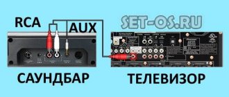
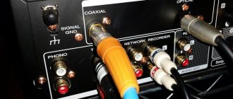
Coaxial digital connection
Perhaps the rarest type of connection in modern audio and video components, coaxial, involves the use of electricity to transmit the audio signal.
The corresponding connector is a familiar round RCA plug that terminates a pair of analog interconnect cables on both sides.
But don't be tempted to use a standard analog RCA cable instead of a dedicated digital coaxial cable! It looks similar and is even quite functional, but its characteristic impedance is lower than that of a digital one (50 and 75 Ohms, respectively), so you won’t get good results. For most systems, an entry-level cable such as QED Performance Coaxial will do just fine.
Today, coaxial connections are less common than optical ones, but they can still be found on the back panels of some AV receivers, amplifiers and televisions.
In our experience, compared to optical, coaxial connections generally provide better sound. It has higher bandwidth, which supports higher quality file formats with up to 24-bit/192 kHz sampling. The optical channel is usually limited to 96 kHz.
The main disadvantage of a coaxial connection is the potential for electrical noise to be carried between devices in the system. It always reduces sound quality and is present to varying degrees in all components. Unfortunately, when using a coaxial connection, noise can be transmitted from the source to the amplifier.
In addition, coaxial cable does not have enough bandwidth to carry high-quality surround sound formats such as Dolby TrueHD, DTS-HD Master Audio, Dolby Atmos and DTS:X. Therefore, the possibilities of its use in a modern home theater system are limited.
Recommendations
- ^ a b c
"SPDIF".
epanorama.net
. Retrieved 2020-08-16. - ^ a b
Toshiba TOTX1701 Technical characteristics of the TOSLINK transmitter module. - "What is TOSLINK?" Frequently asked questions about Toshiba Toslink.
- ^ a b
"Product Guide, TOSLINK™ Fiber Optic Devices" (PDF). 100621 digikey.com - "S/PDIF Information". Intel. July 21, 2022. Retrieved April 3, 2022.
- "S/PDIF". Retrieved April 3, 2022.
- Joseph D. Cornwall (December 31, 2004). "Understanding Digital Interconnections". Audioholics.com. Retrieved 2007-07-12.
- Pendlebury, Ty (December 10, 2015). "Chromecast Audio adds support for multi-room music and high-resolution files." Cnet
. Archived from the original on April 24, 2016. - Greenwald, Will (December 14, 2015). Google Chromecast Audio. PC Magazine
. Archived from the original dated October 4, 2015.
Optical digital connection
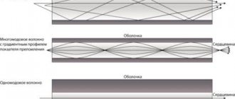
In an optical digital connection, data is transmitted through a fiber optic cable (the fibers of which can be made of plastic, glass or quartz) using light. In this case, noise from the source is not transferred to the DAC circuit, as can happen with a coaxial one, so it is reasonable to use it when connecting the device directly to the DAC of a soundbar or AV receiver.
Traditionally, in DC systems, optical cables are used to transmit compressed multi-channel audio in Dolby Digital and DTS formats. Those with a Toslink connector (Toshiba Link) connect to the corresponding ports of the source and AV receiver. A good starting option is the QED Performance Graphite Optical cable.
Many manufacturers have moved to HDMI as the primary connector type, but optical outputs are still regularly found on devices such as game consoles, Blu-ray players, set-top boxes and televisions. The corresponding inputs can be found on the amplifier or DAC side - for example, in sound bars or AV receivers.
As with coaxial connections, one of the problems with optical connections is the lack of bandwidth to transmit lossless audio formats, such as Dolby TrueHD or DTS-HD Master Audio, which contain most soundtracks on Blu-ray discs. In addition, the optical connection is not capable of transmitting more than two uncompressed channels to the PCM. Finally, the optical cable can be damaged if it is bent too much.
Which optical fiber is better to choose?
I encountered some difficulty in choosing. As it turned out, the choice in length is not as large as it seems. My system is located almost close to the TV, so I simply don’t need too long a wire. That is why you need to clarify in advance how many meters of cable are needed in a given situation.
It should not be a little longer and with a margin, since it cannot be rolled up and tucked behind a TV or audio system. An optical cable with a glass core transmits data with a beam of light and the light inside is reflected from the outer surface. The problem is that if you bend the cable too much, the information may stop being transmitted because the angle of light is too wide.
That is why most often such wires are thick enough to mechanically prevent the optical connection from bending too much. Now you understand that buying with a reserve is a very bad idea and the cable should be freely connected without strong bends. Therefore, when choosing a wire in a store by meter, you must measure in advance the distance from the audio system or speakers to the TV.
Next, buy any suitable cable - they are all almost identical in characteristics. For some reason, many articles write nonsense about the footage, that it is supposedly better to take exactly 5 meters - but this is just nonsense. Since the optics have a long range and do not affect the footage within the apartment in any way. If desired, the cable can even be taken out onto the street or into a neighboring house.
Typical fiber optic cable design
Fiber optic cable design How to connect a television cable
Optical fiber can be made from:
- Polymer;
- Quartz glass.
Polymer fiber is, as a rule, more resistant to mechanical stress and cheaper. However, over time it may lose transparency, which negatively affects the durability of the product.
Glass light guides have better optical characteristics, but are more expensive and fragile.
Why is there a communication jack on a TV?
The word coaxial, translated from Latin, literally means “shared axis,” and the definition of “coaxial” rather refers to a cable whose device ensures high-quality transmission of a high-frequency television signal from the antenna to the TV. That is, the communication connector is the output from the television receiver for connecting an antenna.
The main purpose of coaxial devices is to provide connections between different types of equipment. This connection has two types of paired components: socket-plug and pin-socket. Each cable corresponds to different types of communication outputs.
According to their functional purpose, the following types of connectors are distinguished:
Due to the high cost of copper structures of main communication cables, they are often replaced by optical analogues. They reduce the cost of production due to partial replacement of copper components. The base is made of steel, partially contains clad copper, and is braided with steel and aluminum wires on top.
Based on the assembly method, there are three groups of cable connectors:
Screw-on connectors
The body of the screw-on coaxial output has a built-in rounded thread and is complemented by a press-on nut.
This type of connection connector is also called a screw-on connector. It is especially widely used at home and is very popular due to the ease of connection, the implementation of which does not require special skills or special tools.
However, such common plugs have a number of significant disadvantages:
- fragility, unreliability of the structure;
- the housing ring is not pressed against the nut to the full extent required, as a result of which the connectors are damaged when screwed in;
- the internal thread is insufficient in length, which makes the maximum tightness of the cable fixation impossible and, as a result, causes interference during signal transmission;
- When the plug is screwed onto the cable, the conductors are gradually partially cut/broken, and the protective covering along with the wire braiding is also twisted as it is used.
Crimp connectors
The crimping device uses two cylinders: an outer one, which seems to continue the structure of the housing, and an inner one, which is selected according to the diameter of the cable dielectric with foil. The circular symmetry of the cable is not broken during shrinkage of the outlet. Its body is pressed into a hexagonal prism using a crimping tool.
The antenna crimp connector also features a simplified mounting method.
The characteristics of such connectors may deteriorate due to the use of low-quality materials for their production, as a result of which they quickly wear out.
Compression connectors
The positive properties of compression coaxial outlets with the complexity of their design fully compensate for their relative high cost. They are considered the most reliable, but connecting to them requires understanding the specifics of fastening and the use of special devices.
The advantages of this type of coaxial connectors include:
- anti-corrosion coating;
- operation up to 3 GHz;
- protection from moisture;
- greatest resistance to mechanical stress;
- better shielding compared to others;
- the highest possible resistance to high and low temperatures;
- high tensile strength.
Comparison with HDMI
Computer power cable
Fiber optic communication systems of the early 2000s have a serious competitor. These are devices for transmitting digital information, including an audio signal via an HDMI cable.
HDMI cable
HDMI (High Definition Multimedia Interface) is an interface for high-definition multimedia systems.
The big advantage of an HDMI connection is the ability to simultaneously transmit digital signals, both video and audio, in high quality. Moreover, sound can be sent over eight channels with 24-bit resolution and a frequency of 192 kHz. At the same time, surround sound is easily realized in the speaker system. The HDMI interface is superior to fiber optic systems in terms of the amount of transmitted audio information. For home use, HDMI cables have a length of 1.5-3 meters, but can reach 15 m.
The only disadvantage of an HDMI conductor is the signal transmission through metal conductors. Although they are well shielded, there is still potential for interference from local electromagnetic fields.
Will HDMI replace fiber optics? Not likely in the near future. Many acoustic systems and music centers using optical audio channels have been produced, and their production continues. The consumer will have to choose.
Operating principle and characteristics of S/PDIF
S/PDIF itself is implemented using a “tulip” (RCA) and an electrical (coaxial) cable, where the resistance is 75 Ohms. Such a cord will be an ideal option if the distance between devices is two meters or more. For the shortest possible distances, regular RCA-RCA is also suitable. At the same time, the most progressive option today seems to be the connection option via a fiber optic cable using a laser beam (TOSLINK or OpticalOut).
As noted, S/PDIF is designed to work with stereo audio, but now supports compressed multi-channel audio. This was made possible by expanding the permissible speed from 150 kilobytes per second to 1.536 megabits per second. It uses pulse code modulation to transmit sound. Moreover, the information is split into separate packets (32 bits), and the free space in them can be filled with zeros. In addition to the sound itself, data is transmitted about the number of channels, as well as the track number.
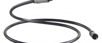
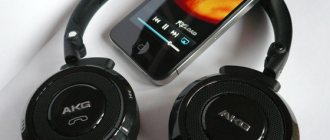
Fiber optic cable for audio devices
Almost all high-quality audio reproduction systems have an optical channel.
Digital audio transmission between remote devices follows the SPDIF (Sony*/Philips* Digital Interface Format) protocol. Its implementation in an optical version was made by Toshiba and became a generally recognized standard called TOSLINK.
Optical audio outputView of the optical digital audio cable of the TOSLINK system
For portable devices, such as laptops, smaller Mini TOSLINK connectors can be used.
Mini TOSLINK connector
Properties and problems
Due to high light attenuation, the effective range of plastic optical cables is limited to 5–10 m.[1] They can fail temporarily or be permanently damaged if they are bent too much. Glass or silica optical fibers, although less readily available and more expensive than plastic optical fiber (POF) cables, have lower loss and can extend the range of the TOSLINK system.
Optical cables are not susceptible to electrical problems such as ground loops and RF interference.[7]
Connection and installation
Before I tell you exactly where to connect the cable, you need to route it correctly. If you chose the right wire, it will be approximately 10-15 cm greater than the distance from the TV to the speakers. As I already said, the “optics” does not tolerate strong bends, since the angle of reflection inside will be too large.
So first, just run the cable. Now, in order to connect the TV to an optical cable, you first need to find this port on the box. It is usually named: Optical Audio, Optical Digital Audio Out, SPDIF or Toslink. The entrance is also usually covered with a plastic cap. Just push the cable slightly and the lid will open. Next, without fanaticism, but confidently connect the cable to the port.
Now we find a similar port on the audio system and connect the second end of the wire. After connecting, turn on the TV and system. In theory, when connected, the audio signal should immediately go to this port. If this does not happen, then check the active audio outputs in the settings. If there is sound, then the connection was successful. If there is no sound, then turn up the volume on the speakers, and also check that the volume level on the TV is not zero. As you can see, connecting an optical cable to a TV is not as difficult a task as it seems at first glance. If you have any difficulties, write about it in the comments.
What about HDMI?
The main advantage of the HDMI standard, introduced in 2002, is the ability to simultaneously transmit video and audio signals. It has significantly higher bandwidth than an optical connection, allowing you to transfer lossless audio files such as Dolby TrueHD and DTS-HD Master Audio. If optical and coaxial connections can be called competitors, then HDMI has no rivals.
HDMI inputs and outputs have long gained a strong position in TVs, Blu-ray players and AV receivers, and are also increasingly found in sound bars. An entry-level cable, such as the AudioQuest Pearl HDMI, will suit a wide range of systems.
The HDMI standard is constantly evolving, with new versions providing ever-widening bandwidth and increased throughput, allowing soundtracks to be transmitted with a greater number of audio channels - for example, in Dolby Atmos and DTS:X formats. It also supports existing and new video formats - including Ultra HD 4K resolution and various versions of HDR - as well as additional features such as high frame rate (HFR) and eARC (supporting up to 32 channels of audio).
Currently, the 2.0 standard is generally accepted, but HDMI 2.1 (supporting 8K content) is gradually making its way to the market.
Types of S/PDIF
Today S/PDIF is implemented in several forms:
- Electric. In this case, a coaxial cable is used, the resistance of which at the input and output reaches 75 Ohms. It connects using RCA connectors. At a distance of up to half a meter, you can use a standard tulip audio cable. Its output voltage is 1 volt p-p, under load - 0.5 volts. If a long cable is used (more than 5 meters), there may be losses.
- Optic. Fiber optic cable (TOSLINK) is involved. This option is distinguished by the operation of a laser beam that does not fade even at significant distances. Particularly popular is the MiniTOSLINK connector, which is very often found in various laptops. it combines headphone and S/PDIF outputs.
So, what type of connection should you choose?
The answer depends on the system you have. If you need to make a choice strictly between coaxial and optical connections, choose the first option. In our experience, a coaxial connection usually provides higher sound quality than an optical connection due to greater detail and increased dynamics.
However, we live in an era focused on maximum convenience. HDMI has become the standard for all audio and video devices today, and it seems reasonable to use it as long as all components in the system have it.
HDMI's functionality, upgradeability, and simultaneous audio and video capabilities make it easy to avoid cluttering cables around your devices. And most importantly, you don’t have to sacrifice quality.
What about the price?
Digital audio is not yet such a proven format as, for example, banner advertising or online video, so there is increased attention to its economic feasibility. “We're still getting familiar with the digital audio format, but engagement and other brand metrics are significantly higher than, for example, video-on-demand pre-rolls,” says Rich Hall, director of research at Havas Media Group.
84% of survey participants claim that the share of digital audio in their media plans will grow, and 80% are going to increase advertising spending in the digital audio segment compared to last year. “Clients are very particular about their budgets and are looking for advertising that works. If you use digital audio and reach people with relevant advertising, and you can prove that it works 15% more effectively, then it's a good investment. Even if advertising costs 5% more, it’s worth it,” says Claire Peters, executive director and head of planning at Manning Gottlieb OMD.
Problems
While advertisers and agencies are unanimous about the promise of digital audio (77% believe it will be a must-have part of any media mix by 2022), the industry has not fully embraced it to date. The results of the MTM study revealed three problem areas: a lack of understanding of the format’s potential for creativity, a lack of understanding of how online audio can be combined with other channels (particularly radio), and issues of measuring the effectiveness of digital audio in the media mix (ROI and attribution model). .
“I don’t remember a time when a client came to me and said: “I have an audio clip, what can you do with it using digital?” It wasn’t like that, but it should be,” says Agenda21 founder Pete Robbins, referring to the fact that clients aren’t taking advantage of features like 3D audio, audio branding (associating a product with certain sounds) and creative ideas based on personalization of the message. However, some clients are struggling to realize the potential - eBay marketing director Gareth Jones talks about his experience: “We sent special briefs to our creative agency to get them to think about the possibilities of 3D listening: how can we exploit people's immersion in online audio? After all, 75-80% of people listen to it on headphones.”
Despite the external similarity of advertising on radio and online audio, these formats should not replace, but complement each other. So far, only those advertisers and agencies who already have experience posting online audio understand this: “We use digital audio to find additional audiences, it is still difficult to measure, but soon we will have a powerful tool for this. There is also an element of creativity - how to convey the message to your audience in a more sophisticated way, including the possibilities of outdoor advertising, banners, etc. Digital audio is more than just an appendage of radio,” says Charlie Yates of Mediacom.
Compared to other, older digital advertising formats (banners, VOD, digital OOH), online audio still suffers from a lack of measurability of its contribution to campaign ROI. “It's hard to say anything about the ROI of audio advertising because it's part of the media mix, and because it's a new channel, there aren't many econometric studies to properly measure it,” complains OMD's Tom Cohar. James Weinberg of m/SIX agrees: “Digital audio is a more expensive format because it is more targeted and premium, and captures a different part of the audience. The advertiser is willing to pay for it, but we don't have convincing information about the ROI. We must see her!
Conclusion
The authors of the study draw several conclusions regarding the demand and prospects of digital audio for the UK advertising market:
- The format gives advertisers a new consumer context - it fits seamlessly into the daily activities of consumers and perfectly complements other activities. Advertisers and agencies value online audio for its high user engagement and one-on-one reach.
- Digital audio is attractive due to new options, including improved targeting, the ability to use dynamic creatives and auction purchases.
With all this, the format must develop, closing those gaps that currently have complaints from clients - in particular, the measurability of the contribution to return on investment. It is also necessary to develop the educational function - the potential of audio advertising is not fully realized.
Sources:
- https://VyborTelevizora.ru/sovety/chto-takoe-digital-audio-out-i-kak-podklyuchit-k-nemu-kabel
- https://televizore.ru/obzor/opticheskij-vyhod
- https://www.audiomania.ru/content/art-7292.html
- https://WiFiGid.ru/raznye-sovety-po-tv/optovolokonnyj-kabel-dlya-televizora-vybor-obzor-podklyuchenie
- https://amperof.ru/teoriya/opticheskij-kabel-dlya-zvuka.html
- https://www.sostav.ru/publication/yuliya-dyachenko-digital-audio-kak-otnosyatsya-k-onlajn-audioreklame-reklamodateli-za-rubezhom-34968.html
Instructions for the audio interface Most-TosLink 3.0 (Most-25)
General description of Most-TosLink and Most-RCA
The MOST-TosLink and MOST-RCA audio interfaces provide the ability to install non-standard audio processing devices, sound processors, power amplifiers and speaker systems into the car. Using these interfaces, audio outputs are created in the car multimedia system, to which non-standard equipment is connected. Both interfaces support broadcasting of all standard service channels (telephone, navigation, parking sensors, service signals). They provide control of standard controls for volume, balance, high and low frequencies and a 5-band equalizer. “Fader” adjustment (sound distribution between front and rear speakers) is supported only by the MOST-RCA interface. The MOST-TosLink and MOST-RCA interfaces do not contain a surround sound processor and multichannel audio decoders, therefore the Logic-7 effect is not supported, and playback of DVD multichannel audio formats (Dolby Digital, Dolby Pro Logic II, DTS, SDDS and etc.) is impossible.
The MOST-TosLink interface produces a 24-bit stereo signal output "TOSLINK optical output (IEC-60958, S/PDIF) 44.1(48)kHz 24 bit stereo PCM".
The MOST-RCA interface creates 3 pairs of analog stereo outputs: front channel (Front Left/Right RCA OutPut), rear channel (Rear Left/Right RCA OutPut) and subwoofer channel (SW Left/Right RCA OutPut).
The MOST-TosLink and MOST-RCA interfaces are connected to the MOST-25 car multimedia network using the MOST-25 optical connector (optoreceiver and optotransmitter), as well as to the car power supply circuit using special power wires (Batt and GND). To control additional equipment, the interfaces have a special “RemoteOut” control output. Adapters can work with different cars. To select the type of car, special contacts with jumpers installed in these contacts (Jumper) are used.
The MOST-TosLink interface uses 6 contacts and 3 jumpers, which determine 1 of 22 possible operating algorithms.
In MOST-RCA, the selection of the algorithm is carried out similarly, but there is an additional pair of contacts. It is used if only the front acoustics are used and you want to switch the sounds of the rear parking sensors to the front acoustics.
About radio interference
MOST-TosLink and MOST-RCA use a switching power supply. To reduce the level of radio interference, the interfaces are mounted in a metal case, which serves as a radio screen. Due to this, the level of radio interference from the operation of the device is insignificant. In addition, the circuitry of these audio interfaces uses electronic components with optimal parameters to reduce the impact on radio reception. The only source of radio interference can be the electrical wires connected to the unit. If the standard radio module is of high quality, the interfaces in question are not capable of interfering with its operation.
If after installing additional equipment the quality of radio reception deteriorates, then the cause may be any installed module, including the MOST-RCA or MOST-TosLink interface. The recommendations below apply equally to any installed module.
How to reduce the impact on radio reception
- do not place the interface and associated wires in close proximity to the receiving radio antenna, antenna cable and units associated with radio reception.
— power wires (Batt and GND) are recommended to be laid together with each other (can be twisted pair). Since the Batt and GND wires create out-of-phase interference, two wires twisted together will have zero activity. If it is impossible to ensure that the power wires are laid together with each other, then the influence of the power wires can be reduced by connecting a capacitor (0.1 ... 100.0 μF, voltage more than 16 volts) with a low ESR value between these wires. The connection location of the capacitor and its value are selected experimentally.
- The location where the power wires are connected to the vehicle wiring can be important. The distance from the interface connection points to the power connection points of the standard radio module is especially important (the result can be affected by both decreasing and increasing this distance).
— it is advisable not to place the RemoteOut control wire in the immediate vicinity of radio receiving nodes. The length of the RemoteOut line should be as short as possible. If it is not possible to use a short RemoteOut line, you can use a shielded wire as this line. The grounding point is selected experimentally (the optimal point may be located near the grounding of a standard radio receiver).
Algorithms of operation for different jumper positions
| Jumper Position | Compatibility | Description |
| Mercedes Benz (audio systems NTG3, NTG3.5, systems with AGW unit manufactured by Becker). | The AGW (Becker) block is significantly larger in size than the AGW (Japan) block. In systems equipped with the AGW (Japan) unit, it is impossible to connect the radio audio channel to an external amplifier. Distinctive feature: systems with AGW (Becker) support the Logic-7 function, but systems with AGW (Japan) unit do not support it. The standard amplifier is stored in the system (combined with a radio tuner). The interface is connected to MOST-25 in front of the standard amplifier (combined with a radio tuner) in the direction of the light. After connecting the interface, the standard amplifier cannot reproduce sound. As of 06.2018, not all vehicle configurations have been tested. | |
| Mercedes Benz 2008+ (NTG2.5, NTG4, NTG4.5 audio systems) | The standard amplifier is dismantled. The adapter connects to any position of the MOST-25 | |
| Mercedes Benz up to 2009 (audio systems NTG1 without external unit AGW and NTG2). | The standard amplifier is dismantled. The adapter connects to any position of the MOST-25 | |
| Mercedes Benz (NTG1 audio systems with AGW external unit) - w211, c219, w220, R171. | The standard amplifier is retained (combined with a radio tuner). The adapter connects to any position of the MOST-25. The standard amplifier remains active and can reproduce sound to the acoustics in normal mode. As of 06.2018, not all vehicle configurations have been tested. | |
| BMW E65, E66 | This mode is recommended when completely replacing the audio system (amplifier and acoustics). The stereo signal is reproduced only by an external non-standard amplifier. The head unit generates only service signals (parking sensors, etc.). To save service signals in the system, you need to connect the acoustics to the head unit. As of 06.2018, not all car configurations have been tested. | |
| BMW E65, E66 | This mode is recommended if you only need to replace the standard amplifier (the standard acoustics are retained). The non-standard amplifier should be connected to the acoustic system that was connected to the removed standard amplifier. A non-standard amplifier only reproduces a stereo signal. The head unit generates service signals to the front and rear speakers and reproduces a stereo signal not to the front speakers. The rear acoustics of the head unit generates only service signals. As of 06.2018, not all car configurations have been tested. | |
| BMW E-series (E60, E61, E63, E64, E70, E71, E72, E90-E93). BMW F-series (F01, F02, F03, F07, F10, F11, F12, F13, F16, F20, F25, F30, F31, F34. BMW G-series | The standard amplifier is dismantled. The adapter connects to any position of the MOST-25. As of 06.2018, compatibility with the BMW G-series has not been fully tested. | |
| BMW E-series (E60, E61, E63, E64, E70, E71, E72, E90-E93). BMW F-series (F01, F02, F03, F07, F10, F11, F12, F13, F16, F20, F25, F30, F31, F34. | A special mode for BMW that uses forced parking sensor signal level parameters. The standard amplifier is dismantled. The adapter connects to any position of the MOST-25. As of 06.2018, compatibility with the BMW G-series has not been fully tested. | |
| AUDI (MMI 2G, 3G) with separate external amplifier | The standard amplifier is dismantled. The adapter connects to any position of the MOST-25. | |
| AUDI (MMI 3G+), Lamborghini (amplifier with radio tuner in a single unit). | The standard amplifier is stored in the system (combined with a radio tuner). The adapter connects to any position of the MOST-25. After connecting the adapter, the standard amplifier cannot reproduce sound. Application features are described in the next section. | |
| Porsche up to 2009 (with PCM2.0 and PCM2.1 control units) | The standard amplifier is dismantled. The adapter connects to any position of the MOST-25. | |
| Porsche 2009+ (with PCM3.0 control unit) | The standard amplifier is dismantled. The adapter connects to any position of the MOST-25. | |
| Volvo S80, XC70 up to 2012, Land Rover Freelander 2 | The standard amplifier is dismantled. The adapter connects to any position of the MOST-25. | |
| LR Freelander 2 (HSE) | The standard amplifier is dismantled. The adapter connects to any position of the MOST-25. | |
| Volvo XC70 2012+ and some Volvo S60, V60 models | The standard amplifier is dismantled. The adapter connects to any position of the MOST-25. | |
| Volvo S60, V60 | The standard amplifier is dismantled. The adapter connects to any position of the MOST-25. | |
| Volvo XC60 Premium | The standard amplifier is dismantled. The adapter connects to any position of the MOST-25. | |
| Volvo XC90, S40, V50. | The standard telephone module is not supported. The standard amplifier is dismantled. The adapter connects to any position of the MOST-25. | |
| LR Discovery-3, Discovery-4 until 2013, RR Sport until 2012. | The standard amplifier is dismantled. The adapter connects to any position of the MOST-25. | |
| RR Evoque, RR Sport after 2012, Discovery-4 after 2013 | The standard amplifier is dismantled. The adapter connects to any position of the MOST-25. | |
| Volvo, Land Rover, Range Rover with activated security coding system | This mode is designed to read the serial number (hereinafter referred to as S/N) from the standard amplifier for the purpose of further use of the S/N by the MOST-TosLink or MOST-RCA interface for correct operation of the system. Reading S/N is only necessary in cases where the security coding system is activated in the vehicle. When the security coding system is activated, the amplification equipment always turns on normally, after which the S/N of all units of the system is checked. If the S/N of the equipment is correct, then the system continues to work, but if the S/N of the amplifier unit is incorrect, then with any change in the sound source the equipment will stop functioning. To read the S/N, the interface is connected to any position of the MOST-25. The stock amplifier must remain in the system during the S/N reading procedure. |
Recommendations for AUDI 3G+ and VW Touareg NF
The AUDI 3G+ and VW Touareg NF multimedia systems standardly use a power amplifier located in a single unit with a radio tuner. For this reason, when installing MOST-RCA or MOST-TosLink, the stock amplifier remains connected to the MOST network along with the installed adapter. A stock system configuration that allows for the installation of an additional external power amplifier is theoretically possible, but there is currently no information on how to program such a configuration. In the event that the standard system is programmed to work with an external separate amplifier, the position of jumpers No. 06 “AUDI 2G” should be used in the MOST-RCA and MOST-TosLink interfaces.
In the general case, when the system is turned on, the standard head unit is connected via the MOST interface not to one, but to two amplifiers (the second amplifier is the connected interface). Since in the basic version the standard system is not designed to work with two amplifiers, this circumstance creates the preconditions for errors when assigning audio channels. During the development of MOST-RCA and MOST-TosLink, relevant research was carried out, as a result of which special algorithms were created to neutralize errors in the assignment of audio channels. MOST-RCA and MOST-TosLink in the AUDI 3G+ and VW Touareg NF systems actually not only fulfill their main task. They monitor the assignment of audio channels and, when an error is detected, cause the system to be reinitialized. Due to the fact that different software versions in automotive systems react differently to the presence of two amplifiers in the system, the problem of error recognition does not have a universal solution at all. A universal solution for the operability of the system in the case under consideration will only be programming the system to work with a separate external amplifier and setting the jumpers to position No. 06 “AUDI 2G”.
As of July 2022, the MOST-RCA and MOST-TosLink interfaces work correctly in most configurations. They record and neutralize those channel assignment errors that have been studied and for which a created algorithm exists. Probably, some of the possible errors have not been studied today and will be studied later.
Recommendations for cases when the AUDI 3G+ or VW Touareg NF system cannot be programmed to work with an external separate amplifier, and when installing MOST-RCA or MOST-TosLink, audio channel assignment errors appear:
— make sure that the adapter you are using has the latest software installed.
— change the position of the interface in the MOST network (it can be installed along the path of the light before or after the standard amplifier unit with a radio tuner). The position of the device in the MOST interface can affect system initialization.
— check the functionality of two different jumper positions in the interface (No. 11 AUDI 3G+, Touareg NF and No. 13 AUDI 3G+, Lamborghini).
— update the software of the standard system.
— if it is impossible to neutralize errors using the described methods, then it is necessary to provide the ability to promptly force the system to initialize (for example, by briefly interrupting the power supply of the MOST-RCA or MOST-TosLink interface) with an external button or refuse to use the interface.
Audio – Most-TosLink and Most-RCA interfaces
developed and manufactured in Russia
) reserves the right
make changes to the design without prior notice,
technical characteristics and software of the product,
not deteriorating its consumer properties
Revision dated 03/28/2019