Microphone preamplifier , also known as a pre-amplifier or amplifier for a microphone, is a type of amplifier whose purpose is to amplify a weak signal to a linear level (about 0.5-1.5 volts), that is, to an acceptable value at which conventional audio power amplifiers.
The input source of acoustic signals for a preamplifier is usually vinyl record pickups, microphones, and pickups of various musical instruments. Below are three circuits of microphone amplifiers on transistors, as well as a variant of a microphone amplifier on the 4558 chip. All of them can be easily assembled with your own hands.
Simple mic preamp circuit without power
Good afternoon
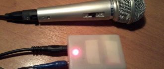
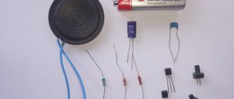
I want to share with you a very simple microphone amplifier circuit. Can be used with a computer headset. Or assemble a completely homemade microphone in a syringe housing. Any electret capsule, which is found in every home, is suitable for this. Such capsules can be found in computer and telephone headsets, in old cassette recorders with sound recording capabilities, etc. A huge advantage of this scheme is that there is no need for additional power. For assembly we need:
1. Transistor BC547 or KT3102 - (1 pc.)
2. Resistors with a nominal value of 1 kOhm (R1 and R2) - (2 pcs.)
3. Resistor with a nominal value of 0 to 1 kOhm (selected for the capsule) - (1 pc.)
4. Disk ceramic capacitor with a nominal value of 100-300 pF - (1 pc.)
5. Electrolytic capacitor 47 uF (6.3 -16 V) - (1 pc.)
6. A piece of a breadboard. Can be used for wall mounting.
All parts will cost from 30 to 60 rubles.
1. Let's start by determining the polarity of the microphone capsule.
The negative contact is always connected to the body (clearly visible in the diagram).
2. Resistors have no polarity. The resistance of resistors R1 and R2 is 1 kOhm. The gain depends on the third resistor (R3) and is selected for the capsule. From 0 to 1 kOhm and the higher the resistance, the lower the gain. In my case, the capsule turned out to be terrible and I needed maximum gain, so instead of R3 I had to install a jumper.
3. The nominal value of the ceramic disk capacitor is 100-300 pF and it has no polarity.
4. An electrolytic capacitor will be needed at 47 uF, the voltage does not matter. I used 6.3 volts, such a capacitor has minimal housing dimensions. The polarity of an electrolytic capacitor can be determined by its markings.
The white stripe on the body indicates the negative contact (clearly visible in the diagram).
5. The main element of the circuit is the bipolar NPN transistor BC547.
You can determine the terminals of the transistor using the diagram.
The first recording was made without an amplifier.
The second one is already with an amplifier, as we can see the sound level has increased significantly.
After assembly, our amplifier can be placed in the syringe body and the open edges can be filled with hot glue. If you want to improve the appearance of the “body”, simply cut off the ears of the syringe and apply heat shrink.
Headphone device
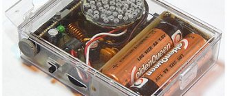
Mobile phone amplifiers are powered mainly by batteries, so it is important to assemble a device with low energy consumption
The instructions below meet this requirement.
If portability is not so important to the owner, you can build in a connector for power from the mains
It is not recommended to use impulse parts as they may cause interference and degrade sound quality.
To create a homemade device, it is better to select the following elements:
- copper cable 30-40 cm;
- adapter input;
- microcircuit KA2209;
- plug input;
- 4 capacitors 100 µF.
The assembly circuit can be used from a similar TDA2822 board. You can avoid using a radiator by mounting the device on a wall-mounted unit.
Do-it-yourself microphone amplifier for a computer
DIY microphone amplifiers.
Amplifier for computer microphone with phantom power.
I installed a program like Skype on my computer. But here’s one problem: you need to keep the microphone close to your mouth so that the interlocutor can hear you well. I decided that the microphone sensitivity was not enough. And I decided to make an amplifier amplifier.
An Internet search yielded dozens of amplifier circuits. But they all required a separate power source. I wanted to make an amplifier without an additional source, with power from the sound card itself. So that there is no need to change batteries or pull additional wires. Before you fight the enemy, you need to know him by sight. Therefore, I dug up information on the Internet about the microphone design: https://oldoctober.com/ru/microphone. The article tells how to make a computer microphone with your own hands. At the same time, I borrowed the idea itself: there is no need to break a ready-made device for my experiments if you can do it yourself. A brief retelling of the article comes down to the fact that a computer microphone is an electret capsule. An electret capsule is, from an electrical point of view, an open-source field-effect transistor. This transistor is powered from the sound card through a resistor, which is also a signal current-to-voltage converter. Two clarifications to the article. Firstly, there is no resistor in the capsule in the drain circuit, I saw it myself when I took it apart. Secondly, the connection between the resistor and capacitor is made in the cable, not in the sound card. That is, one pin is used to power the microphone, and the second is used to receive a signal. That is, it turns out something like this:
Here the left side of the picture is an electret capsule (microphone), the right is a computer sound card. Many sources write that the microphone is powered from a voltage of 5V. This is not true. In my sound card this voltage was 2.65V. When the microphone power output was shorted to ground, the current was about 1.5 mA. That is, the resistor has a resistance of about 1.7 kOhm. It was from such a source that the amplifier was required to be powered. As a result of experiments with microcap, this scheme was born.
The capsule is powered through resistors R1 and R2. To prevent negative feedback at signal frequencies, capacitor C1 is used. The capsule is supplied with a supply voltage equal to the voltage drop across the pn junction. The signal from the capsule is isolated at resistor R1 and fed to the base of transistor VT1 for amplification. The transistor is connected according to a common emitter circuit with a load on resistors R2 and a resistor in the sound card. Negative DC feedback through R1, R2 ensures a relatively constant current through the transistor.
The entire structure was assembled by surface mounting directly on the microphone capsule. Compared to a microphone without an amplifier, the signal increased approximately 10 times (22 dB).
The entire structure was first wrapped with paper for insulation, and then with foil for shielding. The foil has contact with the capsule body.
A microphone with a preamplifier located in the housing requires power wires to be connected to the device (in addition to the shielded signal wire). From a constructive point of view, this is not very convenient. The number of connecting wires can be reduced by supplying the supply voltage through the same wire through which the signal is transmitted, i.e., the center conductor of the cable. It is this method of supplying power that is used in the amplifier we bring to the attention of readers. Its circuit diagram is shown in the figure.
The amplifier is designed to operate from any type of electret microphone (for example, MKE-3). Power is supplied to the microphone through resistor R1. The sound signal from the microphone is supplied to the base of the transistor VT1 through the isolation capacitor C1. The required bias at the base of this transistor (about 0.5 V) is set by the voltage divider R2R3. The amplified audio frequency voltage is released at the load resistor R5 and then goes to the base of the transistor VT2, which is part of a composite emitter follower assembled on transistors VT2 and VT3. The emitter of the latter is connected to the upper contact of the XP1 connector (amplifier output), to which is connected the central conductor of the connecting shielded cable, the braid of which is connected to the common wire. Note that the presence of an emitter follower at the output of the preamplifier significantly reduces the level of interference to the microphone input.
Near the input connector of the device to which the microphone is connected, two more parts are mounted: a load resistor R6, through which power is supplied, and a separating capacitor SZ, which serves to separate the sound signal from the DC component of the supply voltage. The circuit design used in this amplifier ensures automatic installation and stabilization of its operating mode. Let's look at how this happens. After turning on the power, the voltage at the upper terminal of the XP1 connector increases to approximately 6 V. At the same time, the voltage at the base of the transistor VT1 reaches its opening threshold of 0.5 V and current begins to flow through the transistor. The voltage drop that occurs in this case across resistor R5 causes the transistor of the composite emitter follower to open. As a result, the total current of the amplifier increases, and along with it the voltage drop across resistor R6 increases, after which the mode stabilizes.
Microphone amplifier | Transistor amplifier #3
You can assemble a microphone amplifier with your own hands from simple and affordable radio-electronic elements. Such an amplifier is usually built on two stages. One stage is most often not enough, since the signal coming from the microphone has very low power and often needs to be amplified more than 1000 times. In our microphone sound amplifier we will use an electret microphone, which is most widely used. There is a field-effect transistor located in the microphone housing, so the polarity of the connection must be observed. The easiest way to determine the negative terminal is by “continuity” using a multimeter, since it is connected to the housing.
Push-pull model
A push-pull amplifier on a microcircuit is made with field-effect capacitors. Extenders for models are used with different capacities. As a rule, the output sensitivity parameter does not exceed 5 mV. In this case, triggers are used without conductors.
On average, the threshold voltage across the insulators is 12 V. It’s easy to make this type of microphone amplifier with your own hands. For this purpose, a PP20 series microcircuit is selected. The expander itself will be required with a capacitance of around 6 pF. A thyristor is also installed with the capacitors. The conductivity of the signal in this case must be at least 2.2 microns.
A simple DIY electret microphone amplifier
This microphone preamplifier may be needed if you are not satisfied with the volume level of your microphone when recording sound on a computer. Often, in order to enhance the sound from a microphone lavalier, software amplification is done in some sound recording program or video editor, but at the same time the sound itself becomes noisy and distorted. To avoid this, you need to amplify the sound with a preamplifier, to do this, let's solder an amplifier for an electret microphone with your own hands, this is done very simply.
What parts do we need for a microphone amplifier:
- Transistor BC547 or KT3102;
- Two resistors - 1 kOhm;
- One resistor from 150 Ohm to 1 kOhm, selected later by ear;
- Ceramic capacitor from 100 to 300 pF;
- Electrolytic capacitor 47 uF (from 6.3 V and above, but preferably no more than 25 V);
- Electret microphone (lapel microphone).
A simple DIY electret microphone amplifier
How to make an amplifier for a microphone, instructions:
Here is a diagram of a microphone preamplifier, according to which we will solder further.
A simple DIY electret microphone amplifier
This microphone preamplifier is simple, assembled with just one transistor and with a small wiring around it and does not require separate power, since it is designed to work in conjunction with a computer or smartphone. They supply a small voltage that will be sufficient for this microphone amplifier.
A simple DIY electret microphone amplifier
The entire amplifier is assembled on a small piece of a breadboard, which is included in the break of the lavalier microphone wire, which makes it almost invisible if hidden in black heat-shrink tubing. The tracks at the bottom of the board are the terminals of the radio elements themselves, bent and soldered together according to the circuit.
A simple DIY electret microphone amplifier
A simple DIY electret microphone amplifier
A simple DIY electret microphone amplifier
I didn’t immediately solder in resistor R3, first I tried without it, the sound turned out to be very loud and various unnecessary sounds and noises were getting into the microphone, so I started soldering resistors 1 kOhm, 680 Ohm, 330 Ohm and 150 Ohm one by one, listening each time on a smartphone, the most satisfactory sound for me was with a 150 Ohm resistor, which I left.
A simple DIY electret microphone amplifier
A simple DIY electret microphone amplifier
All you have to do is hide the scarf in a heat-shrink tube and your homemade microphone amplifier is ready!
Problem
Most cheap microphones don't have a default sensitivity enough to be heard clearly. You have to scream, but you can’t do that on a regular basis; yelling is a tiresome and harmful activity.
Having carefully studied the issue, I came to the conclusion that the manufacturers are to blame for the situation, overly simplifying the design of the device. Having given his hard-earned 100-500 rubles, the buyer essentially receives a module (capsule) of an electret microphone without any electronic “piping”.
Read also: Three modes of transistor operation
Electret microphone and standard 3.5 mm jack. This design does not allow the microphone to be sensitive, but you can record sound
All sorts of flexible legs and clothespins are optional tinsel. Formally, such microphones work, but their sensitivity and recording quality are low (noise is heard). There's nothing stopping you from adding a few electronic components to the circuit to improve the microphone's ability to pick up quiet sounds.
A typical representative of electret microphones
I'm also not considering purchasing a separate sound card. This was already in the article “How to set up a microphone, record and process sound - instructions for beginners.”
Dynamic microphones already have a built-in amplifier
Amplifier circuits are quite simple, so people who know how to use a soldering iron remake microphones and enjoy life.
Electronics engineers are successfully refining microphones (source)
By the way, even cheap buttonholes for 100 rubles include good electret modules. For example, I have a Genius clip-on microphone from ten years ago, it works great. After modifications, of course.
In addition to low sensitivity, you can hear a low hiss on the recordings. It can be suppressed by filters in an audio editor, but when the interference is too strong, removing noise will distort the useful part of the recording and the voice will sound dull, as if from a barrel.
Noise (in 99% of cases this is interference from electromagnetic fields) appears at several stages of sound delivery:
- In the electret capsule of the microphone.
- In the microphone preamp, if available.
- When transmitting a signal via a connecting cable that is not shielded from interference.
- In the sound card amplifier.
The most painful place is the computer's sound card. Replacing with a better one and/or moving it outside the computer case can get rid of the noise, but not everyone has the money for such an upgrade.
Most often, the user is left alone with a cheap microphone plugged into a loud hissing sound card soldered to the computer motherboard. You can try to make the sound louder programmatically.
How to make a microphone amplifier with your own hands
To make a microphone preamplifier that will take energy not from batteries or not pull long wires from another power source, but so that it is recharged directly from the sound card, you need to make a circuit with a phantom power source. That is, a circuit where the transmission of the information signal and the power supply of the device occur together via a common wire.
This option is the most optimal, because a regular battery often runs out, and using the battery also requires recharging it from time to time. Using the power supply is also not entirely convenient, because there are wires that can interfere with movement and third-party interference. These factors lead to inconvenience in using the device.
Important! The operation of the microphone is based on the property of some materials with increased dielectric permeability to change their charge when exposed to a sound wave. And to amplify the microphone signal, you need to set the resistance in the range from 200 to 600 Ohms, and the capacitance of the capacitor should be up to 10 microfarads.
For this purpose you must have:
- resistors;
- capacitors;
- transistor;
- plug and sockets for connecting the device;
- wires;
- frame;
- microphone;
- additional tools - wire cutters, soldering iron, scissors, tweezers, glue gun.
Additional functions
When buying a microphone preamplifier, first of all, of course, you need to listen and choose with your ears
But then it's worth plugging in your head and paying attention to some factors and features that may be useful to you. The number of inputs means the number of microphones that can be recorded at the same time
The bigger, the better.
The number of inputs refers to the number of microphones that can be recorded simultaneously. The bigger, the better.
- Low pass filter.
Its task is to cut low frequencies, which helps cut off various low-frequency interference.
- Phantom power
, which is necessary for the operation of condenser microphones. By the way, almost all models have it, but make sure of it, just in case.
- Built-in limiter (compressor)
, which is used to compress dynamic range. The limiter also helps to avoid unnecessary overloads. To be honest, this is not a particularly necessary feature, and sometimes it is not worth paying extra for it.
- Level indicators
– an optional feature for every preamplifier, but certainly useful. It's worth paying extra for it.
- Phase switch
will help cope with phase problems when you record several microphones at the same time.
- Equalizer
adjusts the frequencies of the sound signal before sending it to the sound card. Before purchasing, evaluate: do you really need this option?
Amplifier circuit
There are many ways to assemble an amplifier, but this circuit is distinguished by its simplicity and it is based on a classic transistor stage, where a common emitter is installed. Also, to assemble it you do not need to purchase expensive parts. It will take only one hour of free time to make it. The circuit consumes 9 mA of current in operation, and 3 mA at rest.
It has two capacitors and two resistors, one plug, a transistor and an electret microphone. The amplifier board turns out to be very small in size, which can be attached to the plug; if it is slightly larger in size, then you need to take some kind of plastic part to make the case.
The principle of its operation is such that power is supplied to the elements through resistors R1 and R2, in order to prevent feedback in the frequencies of the supplied signal, capacitor C1 is used, and a resistor is needed to eliminate extraneous clicks when connecting a microphone to work. The signal comes from the resistor and goes to the transistor to amplify it. Thanks to this circuit, the signal from a dynamic microphone can be doubled.
Microphone amplifier: step by step
We take a resistor, it will perform the function of biasing the voltage. We take a transistor model KT 315 and can replace KT 3102 or BC847. To make a circuit, we can take a homemade breadboard. Before use, rinse it thoroughly with any solvent. You need to solder the connectors through which the power is supplied; we also use this method to connect the microphone input and output connectors. We take the connectors and solder them to our board. They can be taken from an old DVD player or tape recorder. The switch can be taken from an old toy car. Solder all the parts to the board.
To make a housing for a microphone amplifier, we take a plastic box. We make holes in it for the connectors and for the switch. We glue the board to the box and cover it with the top of the plastic box.
If assembled correctly, the circuit does not need to be further configured and the microphone can be immediately connected to work. This microphone amplifier greatly improves the sound quality and there is no extraneous noise. The circuit also works well with an electret microphone.
Important! Before connecting a microphone to the device, you should check its contacts, and also that the power at the microphone input is at least 5 volts.
If there is no such voltage, then we take another plug and attach it to the connector and measure with a voltmeter the voltage that exists between the large tap and the other two taps, which are shorter. When measuring voltage, you need to be careful not to short the plug terminals to each other.
To check, take a dynamic microphone, connect it, connect the amplifier output with a wire to the computer or speakers, or to the device you need, and turn on the power. If an LED was used during assembly, then its glow indicates that the amplifier is working. But the electrode itself is not required in the circuit.
Microphone preamplifier. Selection of schemes
Microphone preamplifier , also known as a pre-amplifier or amplifier for a microphone, is a type of amplifier whose purpose is to amplify a weak signal to a linear level (about 0.5-1.5 volts), that is, to an acceptable value at which conventional audio power amplifiers.
The input source of acoustic signals for a preamplifier is usually vinyl record pickups, microphones, and pickups of various musical instruments. Below are three circuits of microphone amplifiers on transistors, as well as a variant of a microphone amplifier on the 4558 chip. All of them can be easily assembled with your own hands.
Circuit of a simple microphone preamplifier using one transistor
This microphone preamplifier circuit works with both dynamic and electret microphones.
Dynamic microphones are similar in design to loudspeakers. The acoustic wave affects the membrane and the acoustic coil attached to it. When the membrane oscillates, an electric current is generated in a coil exposed to the magnetic field of a permanent magnet.
The operation of electret microphones is based on the ability of certain types of materials with increased dielectric constant (electrets) to change the surface charge under the influence of an acoustic wave. This type of microphone differs from dynamic microphones in its high input impedance.
When using an electret microphone, to bias the voltage on the microphone, it is necessary to set the resistance R1
Since this microphone amplifier circuit is for a dynamic microphone, when using an electrodynamic microphone, its resistance should be in the range from 200 to 600 Ohms. In this case, capacitor C1 must be set to 10 μF. If it is an electrolytic capacitor, then its positive terminal must be connected towards the transistor.
Power is supplied from the crown battery or from a stabilized power source. Although it is better to use a battery to eliminate noise. The BC547 bipolar transistor can be replaced with the domestic KT3102. Electrolytic capacitors for a voltage of 16 volts. To prevent interference, connect the preamplifier to the signal source and to the amplifier input using a shielded wire. If you need further powerful sound amplification, you can build an amplifier using the TDA2030 chip.
Elementary base
Modern element base makes it possible to create high-quality ULFs based on low-noise operational amplifiers (op-amps), for example, K548UN1, K548UN2, K548UNZ, KR140UD12, KR140UD20, etc.
However, despite the wide range of specialized microcircuits and op-amps, and their high parameters, ULF transistors have not lost their importance at present. The use of modern, low-noise transistors, especially in the first stage, makes it possible to create amplifiers with optimal parameters and complexity: low-noise, compact, economical, designed for low-voltage power supply. Therefore, transistor ULFs often turn out to be a good alternative to integrated circuit amplifiers.
To minimize the noise level in amplifiers, especially in the first stages, it is advisable to use high-quality elements. Such elements include low-noise bipolar transistors with high gain, for example, KT3102, KT3107. However, depending on the purpose of the ULF, field-effect transistors are also used.
The parameters of other elements are also of great importance. In low-noise cascades of electronic circuits, oxide capacitors K53-1, K53-14, K50-35, etc. are used, non-polar ones - KM6, MBM, etc., resistors - no worse than traditional 5% MLT-0.25 and ML T- 0.125, the best option for resistors is wirewound, non-inductive resistors.
The input impedance of the ULF must match the impedance of the signal source - a microphone or a sensor replacing it. Typically, they try to make the input impedance of the ULF equal (or slightly greater) to the resistance of the signal source-converter at fundamental frequencies.
To minimize electrical interference, it is advisable to use shielded wires of a minimum length to connect the microphone to the ULF. It is recommended to mount the IEC-3 electret microphone directly on the board of the first stage of the microphone amplifier.
If it is necessary to significantly distance the microphone from the ULF, you should use an amplifier with a differential input, and the connection should be made using a twisted pair of wires in the screen. The screen is connected to the circuit at one point of the common wire as close as possible to the first op-amp. This ensures that the level of electrical noise induced in the wires is minimized.
Microphone preamplifier with 2 transistors
The structure of any preamplifier greatly affects its noise characteristics. If we take into account the fact that the high-quality radio components used in the preamplifier circuit still lead to distortion (noise) to one degree or another, then it is obvious that the only way to get a more or less high-quality microphone amplifier is to reduce the number of radio components in the circuit. An example is the following circuit of a two-stage transistor pre-amplifier.
In this embodiment, the number of decoupling capacitors is minimized, since the transistors are connected in a circuit with a common emitter. There is also a direct connection between the cascades. To stabilize the operating mode of the circuit when the external temperature and supply voltage change, a direct current feedback loop has been added to the circuit.
Elementary base
Modern element base makes it possible to create high-quality ULFs based on low-noise operational amplifiers (op-amps), for example, K548UN1, K548UN2, K548UNZ, KR140UD12, KR140UD20, etc.
However, despite the wide range of specialized microcircuits and op-amps, and their high parameters, ULF transistors have not lost their importance at present. The use of modern, low-noise transistors, especially in the first stage, makes it possible to create amplifiers with optimal parameters and complexity: low-noise, compact, economical, designed for low-voltage power supply. Therefore, transistor ULFs often turn out to be a good alternative to integrated circuit amplifiers.
To minimize the noise level in amplifiers, especially in the first stages, it is advisable to use high-quality elements. Such elements include low-noise bipolar transistors with high gain, for example, KT3102, KT3107. However, depending on the purpose of the ULF, field-effect transistors are also used.
The parameters of other elements are also of great importance. In low-noise cascades of electronic circuits, oxide capacitors K53-1, K53-14, K50-35, etc. are used, non-polar ones - KM6, MBM, etc., resistors - no worse than traditional 5% MLT-0.25 and ML T- 0.125, the best option for resistors is wirewound, non-inductive resistors.
The input impedance of the ULF must match the impedance of the signal source - a microphone or a sensor replacing it. Typically, they try to make the input impedance of the ULF equal (or slightly greater) to the resistance of the signal source-converter at fundamental frequencies.
To minimize electrical interference, it is advisable to use shielded wires of a minimum length to connect the microphone to the ULF. It is recommended to mount the IEC-3 electret microphone directly on the board of the first stage of the microphone amplifier.
If it is necessary to significantly distance the microphone from the ULF, you should use an amplifier with a differential input, and the connection should be made using a twisted pair of wires in the screen. The screen is connected to the circuit at one point of the common wire as close as possible to the first op-amp. This ensures that the level of electrical noise induced in the wires is minimized.
Preamplifier for electret microphone with three transistors
This is another microphone amplifier option for an electret microphone. The peculiarity of this microphone amplifier circuit is that power is supplied to the preamplifier circuit through the same conductor (phantom power) through which the input signal travels.
This microphone preamplifier is designed to work together with an electret microphone, for example, MKE-3. The supply voltage to the microphone goes through resistance R1. The audio signal from the microphone output is supplied to the VT1 base through capacitor C1. A voltage divider consisting of resistances R2, R3 creates the necessary bias at the base of VT1 (approximately 0.6 V). The amplified signal from resistor R5, acting as a load, goes to the base of VT2 which is part of the emitter follower on VT2 and VT3.
Near the output connector, two additional elements are installed: load resistor R6, through which power is supplied, and separating capacitor SZ, which separates the output audio signal from the supply voltage.
Pre-microphone amplifier based on 4558 chip
The 4558 operational amplifier is manufactured by ROHM. It is characterized as a low power and low noise amplifier. This microcircuit is used in a microphone amplifier, audio amplifiers, active filters, and voltage-controlled generators. The 4558 chip has internal phase compensation, increased input voltage threshold, high gain and low noise. This op amp also has short circuit protection.
Chip 4558 - characteristics
Download datasheet 4558 (140.5 KiB, downloads: 2,822)
microphone preamplifier on 4558
This is a good option for building a microphone preamplifier on a chip. The microphone preamplifier circuit is characterized by high amplification quality, simplicity and does not require much wiring. This dynamic microphone amplifier also works well with electret microphones.
With error-free assembly, the circuit does not require configuration and starts working immediately. The highest current consumption is 9 mA, and at rest the current consumption is around 3 mA.
Additional Information
This version of a homemade preamplifier does not require configuration. Connect the microphone and start recording.
Current consumption (mA):
- during work – 9;
- in standby mode – 3.
The preamp is supplied with phantom power, i.e. its source is the sound card itself. In such options, the supply wire simultaneously transmits the signal from the microphone. Alternative nutrition methods have disadvantages:
- batteries have to be changed periodically;
- connecting to an outlet via a power supply, additional wires appear.
This version of a homemade preamplifier does not produce noise interference and improves sound quality. Works with both dynamic and electret microphones.