REEL TAPE RECORDER AS THE MAIN SOURCE OF SOUND IN A STEREO SYSTEM
Reel-to-reel tape recorder as the main source in a sound reproduction system.
The sound source is one of the important components of any sound reproduction system. Recently, there has been a growing interest in analog audio sources. These include: turntables, reel-to-reel tape recorders and cassette decks. Vinyl disc players and cassette decks have already been covered in detail on this site, and the purpose of this article is to justify the choice of a reel-to-reel tape recorder as the main sound source in a sound reproduction system of any level.
AEG released the first commercial tape recorder, the Magnetophon K1, in 1935.
The word Magnetophon itself has long been a trademark of AEG-Telefunken, although it soon became a common noun in a number of languages, including Russian. After the end of World War II, AEG-Telefunken tape recorders were exported from Germany to the USSR and the USA, where a few years later (in America - in 1947) similar devices were created.
Subsequently, the design of the reel-to-reel tape recorder was constantly improved.
The reel-to-reel tape recorder (Master Recorder) has long been used as the main source for the production of master tapes, from which matrices were then made for the production of vinyl records.
Magnetic sound recording was truly a massive audio format for several generations of listeners around the world. Many record labels published entire catalogs of reel-to-reel releases. There are still vinyl records on the sleeves of which you can find three catalog numbers for a given release: on a vinyl record, on a compact cassette and on a reel-to-reel. Currently, constantly improving digital technologies have pushed magnetic sound recording into the background, and it has turned out to be undeservedly forgotten. And although some well-known studios still have an analogue recording department, a renaissance on a mass scale is still a long way off.
In this article we will try to return magnetic sound recording to its former greatness. Let's start with general provisions about the design of a reel-to-reel tape recorder and its main technical characteristics.
Classification of reel-to-reel tape recorders:
- Based on the type of media, tape recorders are divided into tape and wire. In addition, devices using a magnetic disk or cuff are known;
- According to the method of recording information, tape recorders are divided into analog and digital;
- By area of application, tape recorders are divided into studio, household and industrial (the latter type was previously widely used not only for recording audio information, but also for recording analog data, for example, signals from analog temperature, pressure sensors, etc. in industrial processes or laboratory research) ; industrial tape recorders for recording data are also called magnetographs in some sources;
- By the presence of a built-in power amplifier - for full tape recorders and set-top tape recorders (slang “deck” from the English deck - panel).
- In terms of mobility - wearable, portable and stationary;
- By the number of played and recorded tracks: 1, 2, 4 or more;
- Based on the speed of media movement during recording and playback. The most common standard speed values when using magnetic tape: 76.2 (old-style studio tape recorders), 38.1 cm/s (household and studio tape recorders); 19.05 cm/s (household and studio tape recorders); 9.53 cm/s (household and studio tape recorders).
There are multi-speed tape recorders, tape recorders with other speed values, as well as with changing tape speed as it is rewinded;
- By the number of heads: one (reproducing only, in tape recorders), two (the most commonly implemented option: the first, in the direction of the tape movement, is the erasing head, then the universal one, which can both record and reproduce information), three ( the so-called “through path” - separate specialized heads are used for recording and playback), four (with an additional playback head that operates when the tape moves in reverse), less often - more;
- By recording and playback format: monophonic, stereophonic, quadraphonic, multi-channel;
- studio tape recorders - by design: console, desktop, rack.
Technical characteristics of a reel-to-reel tape recorder.
Mechanical:
- deviation of the carrier speed from the nominal one – %;
- detonation coefficient (unevenness of belt speed) – %;
Electrical:
- frequency range (of the recorded signal);
- frequency response unevenness (in the operating frequency range) dB;
- coefficient of nonlinear distortion (THD, THD)%;
- dynamic range, dB;
- signal-to-noise ratio, dB;
- output power, W (for devices with UMZCH);
Reel-to-reel tape recorder
The main functional units of a tape recorder are a tape drive mechanism (TMM), a block of magnetic heads (BMG, BVG) for recording, playing back and erasing signals, and electronic devices that ensure the operation of the MMG.
Tape transport mechanism
The tape drive mechanism, or the mechanism for transporting magnetic tape, ensures, as the name implies, the transport of magnetic tape. The characteristics of the CVL have the greatest impact on the quality of sound reproduction of the device as a whole, because the distortions that a non-ideal CVL introduces into the signal cannot be corrected by any correction in the analog electronic path. The main characteristics of the CVL are the detonation coefficient and long-term stability of the belt speed (expressed as a percentage of the largest deviation of the speed from the nominal one).
The LPM must provide:
- uniform movement of the magnetic medium during recording and playback at a given speed (stroke);
- uniform tension of the carrier with a certain force;
- uniform and reliable contact of the media with the magnetic heads;
- switching belt speeds (in multi-speed models);
- accelerated rewinding of the media, as a rule, in both directions - forward and backward (in the simplest and special devices, rewinding may be absent);
- additional features depending on the class and purpose of the tape recorder: auto-stop, short-term stop during the working stroke (pause), reverse (recording and playback in both directions), automatic search for fragments of a phonogram, tape counter, etc.
To drive CVLs, as a rule, electric motors of direct and alternating current are used. Some early portable models used spring (gramophone-type) motors to save battery energy, for example, in the Soviet MIZ-8 and Dnepr-8, and the Swiss Nagra I and Nagra II. Friction, belt and gear drives are used. A CVL can contain one engine, two or three, rarely more. The single-engine design is the most common. Two or three engines are usually installed in expensive high-quality devices. Three-motor CVLs are considered the most advanced. They have the least number of mechanical gears, the driving unit is best isolated from the influence of the receiving and supply units (which means it is easier to stabilize the speed and tension of the belt). But these advantages are fully realized only with the use of special and very expensive precision motors.
According to the principle of controlling operating modes, CVLs come with mechanical and electronic control.
- In a mechanically controlled CVL, the movement of individual components (pressure roller, block of magnetic heads, mechanical transmission elements) occurs under the influence of mechanical force from buttons, keys or control levers. Their advantages are simplicity, reliability, and low power consumption. Disadvantage - it is very difficult to implement automatic control of operating modes (auto search, etc.).
- In an electronically controlled CVL, the force to move all components is created by electromagnets and auxiliary electric motors. They are controlled through an electronic logic circuit (often on a microcontroller or microprocessor). Such a CVL can easily be automated (auto-search functions, remote control, recording level calibration and magnetization for a specific type of tape).
The specified characteristics of the CVL are ensured by careful design of the mechanism, precision manufacturing of parts and assemblies, and the use of electronic, mechanical and electromechanical systems for automatic stabilization of speed and belt tension.
A standard range of tape pulling speeds appeared in the mid-fifties. Before this, there was no single standard, which can be explained by two reasons:
- Many models of the first tape recorders were developed for recording synchronous phonograms during film production and were designed for continuous perforated magnetic tape, the same size as 35 mm and 16 mm film. Therefore, in the CVL of tape recorders, as well as in the CVL of optical sound recording devices, gear drums were used, and speeds of 18 and 46.5 cm/sec, standard for the same film formats, were used. This simplified the synchronization of image and sound during editing and subsequent conversion of magnetic phonograms into optical ones.
- In Germany, where magnetic recording developed most intensively before World War II, metric speeds were adopted. After the war, most of the German documentation on tape recorders came to the USA, where, as American developments progressed, mechanical parameters were converted from the metric system to the inch system. So the speed of 75 cm/sec turned into 76.2 cm/sec (30 inches/sec), etc. The most intensive work on magnetic recording was carried out, so eventually the inch range of speeds spread throughout the world.
Magnetic heads
The most important component of a tape recorder is the magnetic heads . Their characteristics largely determine the quality of the device as a whole.
The magnetic head can work with either one track (mono) or several - from two (stereo) to 24 (see Multi-track recording).
They are classified by purpose: playback heads ( GV ), recording heads ( GZ ), universal record-playback heads ( GU ) and erase heads ( GS ). The number of them installed on a CVL varies from one (GV in tape recorders or GS in tape recorders intended only for recording), two (GU and GS - the most common option in household tape recorders), three (GV, GS, GS - so called “through channel”, which ensures playback of the just recorded signal) up to four (two GV for the reverse function and one GZ and GS) or more (one head for the “reverse” function can be used, but with a 180° flip mechanism or height shift).
In the case of using several heads in a common structure (drum, base), they talk about a block of magnetic heads (BMG) - for example, there are audio recorders with replaceable MMG, which allows you to get, for example, a different number of tracks (German high-end household tape recorder Uher Royal de Luxe, 1969). Sometimes combined heads are used, which structurally combine, for example, GU and GS. Also, sometimes a separate head is used for magnetization, recording and playback of auxiliary signals, etc. Erasing the recording is usually carried out by a high-frequency alternating magnetic field, but in the cheapest models, the GS was widely used in the form of a specially shaped permanent magnet, which is mechanically applied to the tape when erasing, despite the fact that the noise level when erasing with a constant magnetic field is greater.
The quality of the magnetic heads used mainly determines the quality of signal recording/playback in the tape recorder. Its durability (service life) also depends on the quality of the head. The first models of cassette tape recorders had heads with a core made of soft permalloy; later they were replaced by more wear-resistant heads made of glass ferrite and sendust. Later, magnetic heads made of amorphous metal (A-heads), characterized by excellent magnetic properties and wear resistance at the level of glass ferrite, and high-quality magnetoresistive heads (Z-heads) were developed.
Correct alignment of the magnetic heads (their spatial arrangement in height and inclination relative to the tape) in accordance with accepted standards is important to ensure the compatibility of recordings made on different tape recorders. The compatibility of recordings is especially strongly influenced by the coincidence of the azimuths of the magnetic heads (the angle between the magnetic gap of the head and the edge of the tape) during recording and playback. A mismatch of azimuths by just a few arc minutes leads to a sharp deterioration in the reproduction of high frequencies. Cheap tape recorders often have a special hole in the front or rear panel for adjusting the head “by ear” to the maximum reproduced high frequencies.
During operation, the magnetic heads become clogged with the magnetic layer falling off the tape and therefore must be periodically cleaned.
Electronics
The electronic part of the tape recorder consists of:
- one or more (according to the number of channels) playback amplifiers ( UV ) and recording amplifiers ( US ). In simpler models, the functions of ultrasound and shock wave are combined in a universal recording/playback amplifier ( RU );
- one or more (according to the number of channels) low-frequency power amplifiers, to the outputs of which internal or external speaker systems and/or headphones are connected.
- erasure-bias generator ( GSP );
- noise reduction devices (optional);
- electronic control systems for CVL operating modes (optional);
- various auxiliary units: signal level indicators and operating modes, switching devices, remote control, etc.
A distinctive feature of ultrasonic and ultrasonic tape recorders is that they necessarily contain frequency correction circuits configured in such a way as to compensate for frequency distortions introduced by the heads and tape, and to ensure the maximum possible linearity of the frequency response of the recording-playback channel. The parameters of the shock wave correction circuits (their “time constants”) are standardized for various speeds and types of tapes, and the frequency response of the recording amplifier is selected such that, when played back through a standard waveform, a uniform frequency response of the entire path is obtained in a given frequency range. In this way, compatibility of recordings made on different tape recorders can be ensured. If a tape recorder is designed to operate at different tape speeds or with different types of tapes, its HF and ULTRASONIC tape recorders contain manual or automatic switches for correction circuits (triggered by special recesses on the body of a compact cassette with a certain type of tape). In addition, the CF must be as low-noise as possible, since the signal from the playback head is usually very small and amounts to hundreds of microvolts at the maximum signal level.
The signal voltage at the UV output is hundreds of millivolts. Then it is fed through the volume and tone control to the input of the low-frequency power amplifier, and also (if the tape recorder has a linear output) can be fed to the input of external amplification and signal processing devices.
The GPS produces a sinusoidal voltage necessary for magnetization during recording and for erasing the recording. The GPS frequency is selected 4-5 times higher than the upper limit of the frequency response of the tape recorder, that is, from 40-50 kHz for the simplest devices and up to 85-210 kHz in Hi-Fi class models. Miniature tape recorders often use permanent magnet erasure. This makes it possible to use a generator of significantly lower power for magnetization. In the most primitive tape recorders there is no GPS at all, and magnetization is produced by supplying direct current to the recording head.
More advanced models contain devices for indicating operating modes and recording-playback levels (analog or digital), auto-stop sensors, an auto-search system (AMS, APSS, etc.), an automatic recording level adjustment device (ARUZ), a noise reduction device (like compander systems - Dolby B, Dolby C, Dolby S, DBX, Hign Com and dynamic filters - DNL, "Mayak"), "dynamic bias" block (Dolby HX, Dolby HX Pro, SDP, SDP-2, etc.), switch inputs/outputs (“Monitor” mode) and some others.
Element base
The electronic part of the first tape recorders was, naturally, carried out using vacuum tubes. Tubes in a tape recorder pose three specific problems.
- First, the lamps generate a lot of heat, which can damage the magnetic tape. In stationary tape recorders, the electronic circuit was either implemented as a separate unit, or special measures for ventilation and thermal insulation were provided in a spacious case. In portable small-sized models, they tried to reduce the number of lamps and increase the area of ventilation holes. The instructions often specified a maximum time for continuous operation of the tape recorder, usually several hours, and recommended not to leave the tape on the machine while it cooled.
- Secondly, the tubes are prone to microphonic effects, and the tape mechanism creates quite a significant amount of acoustic noise. In high-end tape recorders, it was necessary to take special measures to combat the microphone effect, for example, installing the input tubes of recording and playback amplifiers on shock absorbers.
- Thirdly, lamps require a high-voltage power supply for the anode circuits and a low-voltage (but quite powerful) one for heating the cathodes. The tape recorder also requires a power source for the electric motor. Thus, a set of batteries for a portable tube tape recorder could turn out to be quite bulky, heavy and expensive.
With the advent of transistors, they began to be used in tape recorders. The problems of heat generation and microphone effect were automatically solved. The transistor tape recorder could be powered by inexpensive low-voltage batteries, and they lasted much longer. Tape recorders have become truly portable. During the 1960s. tube tape recorders were almost completely forced out of the market by transistor ones.
Since the 1970s, analog integrated circuits have been increasingly used in tape recorders, both general-purpose (operational amplifiers) and specialized (low-noise HF, UMZCH, compander noise suppressors, etc.). Control circuits use digital microcircuits of varying degrees of integration, up to microcontrollers and microprocessors.
Comparison of electrical parameters of reel-to-reel tape recorders with digital sources and vinyl record players.
Reel-to-reel tape recorders use magnetic tape as a carrier, wound on plastic or metal reels (in everyday life the name “reel” was also used; before the advent of cassette tape recorders, reels were called cassettes) or on cores without cheeks (to prevent the tape from falling off, tape recorders designed for cores have disks on the supply and receiving units - “plates”, “pancakes”, there are also collapsible reels with removable cheeks). The tape is wound with the working layer inside the roll, but in very old tape recorders it was often found that the working layer was wound outward. At the same time, sometimes the tape was wound onto the take-up reel inside out - with the working layer inside, so that it was impossible to mistakenly start recording backwards (for example, the first Dnepr models).
Due to the wide tape and its high speed, reel-to-reel tape recorders can provide very high quality recording and playback, higher than the quality of mechanical recordings, CDs and compact cassettes.
In addition, it must be remembered that until the early 1990s, master tape was the only source of matrix production for vinyl production, and in the 1980s and 1990s, master tape was also used for the production of master discs.
Currently, when re-releasing remastered releases on digital media, the basis for remastering still remains exclusively the master tape!
Some disadvantages of magnetic sound recording include the bulkiness of the equipment, the need for regular maintenance and repair, the high cost of the tape and the large size of the reels, which require a lot of storage space. With the right choice of reel-to-reel tape recorder, all these inconveniences more than pay off, and we will talk about how to make this choice correctly below.
Tips for choosing a reel-to-reel tape recorder.
First of all, you need to decide whether you will record phonograms on magnetic tape yourself or prefer to buy ready-made high-quality recordings. Of course, if finances allow, it is best to combine these activities. Having at your disposal a professional reel-to-reel tape recorder, for example: Tascam BR 20 or Otari MX 5050 and a high-quality pre-amplifier, you can easily correct the frequency response of the original phonogram at your discretion and get a result with better quality than the original one.
If your budget does not allow you to go so wide, you can purchase a reel-to-reel tape recorder at your own expense and then simply purchase high-quality recordings and listen to them. Moreover, in this matter there is a wide field for maneuver: perfectionists can purchase: Studer A807 , Studer A810 , Otari MX55 , Tascam BR 20 , as well as Technics RS 1500, 1506, 1520, 1700 tape recorders (the latter is the most expensive on this list ).
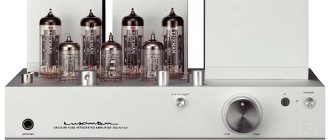
TECHNICS RS 1700
Middle-income music lovers can purchase reel-to-reel tape recorders such as ReVox A/B 77 , Sony TC 755/765 , Teac 1000/2000/3300 , Pioneer RT 909 , Akai GX 635/646/650/747, Tandberg TD 20 , Denon DH- 610S and some others.
It should be remembered that Akai GX 635/646/650/747 reel-to-reel tape recorders, unfortunately, have weak side winding motors and glass ferrite heads, which give the sound a specific coloring.
Music lovers with a limited budget may well limit themselves to Soviet reel-to-reel tape recorders of the highest complexity group - Electronics 004 or Olympus 003/004/005 .
With minimal maintenance, these reel-to-reel tape recorders will provide you with very high quality sound reproduction.
In this case, it is best to purchase tapes with high-quality recordings from reliable sellers who produce these phonograms using high-quality equipment.
Playing time of 1100 m of tape (reel No. 27 or 10.5”) at a speed of 19.05 cm/s is 180 minutes.
This is enough to record four vinyl records on such a tape.
In my opinion, there is no point in purchasing studio master recorders such as Studer A80/A 820/C 37/, Otari MTR-BTR, Ampex-ATR 102, Tascam ATR 60, MCI and the like. The fact is that such master recorders reveal their full potential only with the support of additional equipment for dynamic sound processing. In fact, you will have to build a real mastering laboratory at home with a budget of $100,000 or more. Otherwise, you will not hear anything extraordinary in sound from such a master recorder.
How to choose a reel-to-reel tape recorder.
If there is such an opportunity, you need to choose a reel-to-reel tape recorder yourself.
Key points to pay attention to:
- Appearance.
— The degree of wear of the heads and tape drive mechanism. To do this, you need to arm yourself with a flashlight and a magnifying glass with high magnification and carefully inspect all these components, be sure to pay attention to the safety of the rubber rollers and rubber rings on the bypass rollers.
— Condition of the drive capstan, check the lubrication and play on it.
— Check the operation of the tape recorder in all modes: rewinding in both directions, recording, erasing and playback.
— Check the smooth operation of the tape transport mechanism, the absence of jerks and sagging of the tape.
— Check for the absence of extraneous mechanical noise and sounds.
— It is advisable to open the reel-to-reel tape recorder and inspect it inside for the absence of foreign interference in the mechanical components and electronics. Check the condition of the belts.
Tips for repairing and maintaining a reel-to-reel tape recorder.
The most important advice: “Don’t skimp on brewing!”
Don’t expect to buy a faulty reel-to-reel tape recorder cheaply, in the hope that some local “Kulibin” will then restore it for you for half a liter.
There are no miracles!
You need to buy a fully functional, calibrated, working tape recorder!
In this case, if you use your tape recorder as usual, and do not kill it by duplicating it, prevention will only consist of periodically wiping the heads with isopropyl alcohol.
If qualified repairs are required, try contacting the nearest licensed radio electronics service center.
If you want to use your reel-to-reel tape recorder for duplicating phonograms, you will have to look for a good service technician and a set of MRL test tapes for regular qualified maintenance.
Tips for purchasing magnetic tape.
If you plan to buy only ready-made phonograms, this issue is resolved automatically - you buy the tape on which the seller writes.
If you want to record the phonogram yourself or you want the seller to record the phonograms you have chosen on your tape, then you need to consider several important points:
— First of all, you need to decide on the type of tape.
Tape for studio recording with a thickness of 50-54 microns is very high quality, reliable, resistant to the copy effect, increased impact and resistance to overloads.
An ordinary tape for household recording with a thickness of 35 microns is quite sufficient for domestic use.
Conventional tape for household audio recording with a thickness of 25 - 27 microns requires a precisely adjusted tape drive mechanism, and, as a rule, becomes deformed during operation.
— It’s best to buy a new tape that is still produced, for example,
factory - RMG (Recording The Masters (MULANN Group).
— Of the used tapes that are offered on the secondary market, it’s probably worth paying attention to the Maxell tape, but we must take into account that a lot depends on where and under what conditions this tape was stored by the seller.
The cost of household tape on a 10.5” reel ranges from $15-$100 per reel, depending on the type of tape and its condition.
Where and how to purchase phonograms.
Currently, there are several foreign Rec labels that record phonograms on their tape. But their prices are too high, and the sound quality of the phonogram is digital, not analog:
https://www.openreelrecords.com/
https://www.abcrecord.com/en/
https://tapeproject.com/
Used phonograms of varying quality periodically appear on the secondary market, but it is impossible to assess the condition of the tape and the sound quality of the phonogram in absentia.
Taking this into account, we would like to draw the attention of potential magnetic sound recording enthusiasts to domestic manufacturers .
Price list for the new tape Recording The Masters (MULANN Group).
RMG LPR90 #38512 1/4″ 1100 m PLASTIC REEL 10″ Trident Hinged 4000 rub. RMG LPR90 #38520 1/4″ 1100 m METAL REEL 10″ NAB 5500 rub. RMG LPR90 #38530 1/4″ 1100 m PANCACE NAB 10″ ECO 3200 rub. RMG LPR35 #34512 1/4″ 1100 m PLASTIC REEL 10.5″ Trident Hinged RUR 3,700 RMG LPR35 #34520 1/4″ 1100 m METAL REEL 10.5″ NAB Hinged 5000 rub. RMG SM911 #34112 1/4″ 1100 m PLASTIC REEL 10.5″ Trident Hinged 3500 rub. RMG SM911 #34120 1/4″ 762 m METAL NAB 10.5″ Hinged 4800 rub. RMG SM900 #34620 1/4″ 762 m METAL NAB 10.5″ Hinged 5000 rub. RMG SM900 #34621 1/4″ 762 m PLASTIC REEL 10.5″ Trident Hinged RUR 3,000 RMG SM900 #34630 1/4″ 762 m PANCACE NAB ECO RUB 3,700 EMTEC PER 528 1/4″ 1000m AEG — 3500 rub. Leader RMG 1/4″ LEADER TAPE 250M / NAB HUB RED — 1500 rub. Leader RMG 1/4" LEADER TAPE 250M / NAB HUB GREEN - 1500 rub. Leader RMG 1/4" LEADER TAPE 250M / NAB HUB TRANSPARENT - 1500 rub. Leader RMG 1/2" LEADER TAPE 250M / NAB HUB WHITE — 3000 rub. Leader RMG 1/2" LEADER TAPE 250M / NAB HUB RED - 3000 rub.
Empty Hinged Box 10.5″: 1/2″-1350 RUR.
In the context of this article, we need to especially consider a very important issue - the advantage of the sound of copies from master tapes over digital media and vinyl records.
Currently, there is confusion in the understanding of the term “Master Tape”, caused by the fact that publishers put the “Master” stamp on everything that came to their hands. In the most general case, the “Master” mark on a box of magnetic tape simply means that this tape will be used as the source phonogram in some process. This is how circulation copies, broadcast copies, technical copies and many others appeared. And each copy also proudly bore the “Master” mark. All these copies were made from different sources, such as a vinyl record. In the process of making such copies, rather harsh and merciless dynamic sound processing was used. It is not recommended to use such copies for listening.
Therefore, first of all, it is necessary to define what a “Master Tape” is, copies of which can be used in order to hear all the advantages of magnetic sound recording. The process of studio sound recording technologically looks something like this: performers in the studio are recorded through microphones on a multi-channel tape recorder using the minimum necessary dynamic sound processing. Next, a multi-channel phonogram (multi-track), also using the minimum necessary dynamic sound processing, is recorded on a two-channel tape recorder (Master Recorder). The two-channel phonogram obtained in this way is sent to the mastering laboratory. In the mastering laboratory, engineers carry out, so to speak, the final tuning of the resulting phonogram so as to obtain the highest possible sound quality, approved by standards and satisfying the record label producers. After this, the “Master Tape” obtained in this way is sent to a workshop either for the production of digital media or for the production of vinyl records. In these workshops, local engineers perform additional dynamic processing of the sound of the original phonogram, which increases the nonlinear distortion of the resulting copy.
In addition, the vinyl record production technology itself uses RIAA correction. The essence of this correction is that when cutting a varnish disc, due to a number of technological axioms of electromechanical sound recording, low frequencies are suppressed and high frequencies are raised. When playing vinyl records, the phono stage performs reverse equalization: it raises low frequencies, and lowers high frequencies. Thus, in the process of electromechanical sound recording (playback), at least three more stages of the appearance of nonlinear and dynamic distortions of the phonogram occur: the nonlinear process of mechanical cutting of the varnish disk, the nonlinear process of direct RIAA equalization and the process of reverse RIAA equalization.
In the case of using MC cartridges and a Step Up transformer, several more quite serious sources of nonlinear and dynamic distortions appear, for example, electromagnetic processes in the magnetic core and windings of the transformer, etc.
The copy from the “Master Tape” is devoid of all the nonlinear and dynamic distortions described above and therefore sounds much better - cleaner, more natural, larger-scale. You can get a vague idea of the sound of such a recording by listening to a test digitization . The recording was made from a master tape onto a compact cassette, played back on a Nakamichi cassette deck and digitized by a TASCAM-DA3000 recorder in 192/24 WAV format.
Author of the article Andrey Rufinovich especially for hiendmusic.ru
If you are planning to build a system from scratch or want to improve your existing setup, take a look at the hiendmusic . ru , where the most interesting components are collected in terms of price/quality ratio.
If you have the financial capacity to build a truly top-of-the-line system, then a personal consultation .
Personal consultation hiendmusic . ru will help you:
— purchase components that are ideally matched to your musical taste and get an absolutely magnificent sound;
— purchasing a set of the highest level is 20-30% cheaper than in any music store, since the components will be purchased at the best prices from various suppliers. Stores, as a rule, are interested in increasing sales volume and offer several components at once, some of which are not the best match, and some are sold at an inflated price - as a result, the buyer purchases a worse set and for more money than he could have. Consultation hiendmusic.ru will help you make your purchase cheaper and get a higher sound level!
— save another 5-10% of the cost of the kit by refusing to purchase unnecessary options;
To order a consultation, simply write to [email protected]
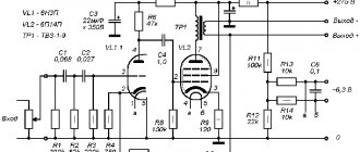
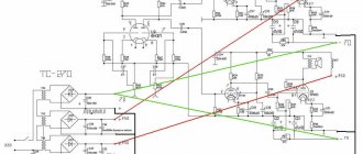
Circuitry of modern tape recorders, page 4
The electric motor control circuit generates the required voltage at pin 13. In this case, the rotation speed of the electric motor M, connected between the specified pin and the power source wire, can be regulated by a variable resistor R4. The operating modes of the said circuit are controlled by switches SW2 and SW3.
A number of domestic models of tape recorders use the K157UL1A(B) microcircuit as a playback amplifier. It operates at a supply voltage of 9 V (the permissible range of variation of this voltage is 8.1-20 V). In nominal mode, current consumption is 3-6 mA. The circuit is optimized in terms of the signal-to-noise ratio provided (this parameter has a value no less than 54 dB). The microcircuit has a built-in supply voltage stabilizer, and the output stages are short-circuit protected.
The schematic diagram of the UV on the K157UL1A IC is shown in Fig. 3.22. The amplitude-frequency characteristics of channel amplifiers are determined by the parameters of the negative feedback circuits connected between pins 13, 1 and 9, 7, and the gains are determined by the resistances of resistors R3 and R4.
Playback amplifiers can be included in larger microcircuits that combine several tape recorder units. Such structures will be discussed below.
Microcircuits for building recording amplifiers
One of the requirements for recording amplifiers is their high output impedance, due to which they work as current generators. Naturally, any amplifying microcircuit cannot act in this capacity. In addition, it is necessary to be able to change the parameters of the correction circuits when using different types of magnetic tapes and different recording speeds. If the dynamic range of the recorded signals is large, there is a need for an automatic recording level control system (ARL).
In Fig. Figure 3.23 shows the block diagram and connection diagram of the LA3220 chip used in the JVC UX-T20 music center.
The inputs of the left and right recording channels are the 1S342/5D0 pins, and the outputs are 1S342/2DZ. Corrective RLC circuits that determine the type of frequency response are included in the negative feedback circuits of the amplifiers, that is, they are connected to the terminals 1S342/2D and 1S342/11D. When changing the type of magnetic tape, the control voltage RCRO2 is supplied to the bases of the key transistors Q143 and Q243, and additional switching is performed correction chains R152R153C157 and R252R253C257, changing the time constants of the recording paths. ARUZ cascades are designed independently of the main recording amplifiers. For them to work, a signal proportional to the average level of the signals in the channels must be applied to the pin of IC342/7. The recording level is adjusted by changing the output resistance of the ARUZ cascades (outputs IC342/6.9), connected in parallel to the circuits for passing the recorded signals. To turn off the ARUZ circuit, key transistor Q343 is used. When a logic high voltage is applied to its base, it opens and the low output resistance of the collector-emitter junction bypasses the control pin of IC342/7.
Among the domestic developments of such microcircuits, we can name ICs K157UP1 and K157UP2. These modifications differ in the location of the terminals and the polarity of the control voltage of the ARUZ system. In Fig. Figure 3.24 shows a block diagram of these microcircuits. The pin numbering is given for the K157UP1 IC. The circuit contains two channels of a stereo recording path, consisting of preliminary ultrasound with gain control circuits and microphone amplifiers. Its advantage is the low level of its own noise. The overload capacity at the microphone input is 36 dB, and at the input of the recording preamplifier - 16 dB.
Microcircuits for constructing complete recording/playback paths
Some models of tape recorders use a combined recording/playback path, where the same amplification stages are used using switching elements in both playback and recording modes. This is necessary in order to maintain a certain compromise between the requirements for amplifiers. High-quality equipment does not use such circuit solutions.
There are integrated circuits (Table 3.5) containing both elements of a combined path and cascades designed for separate operation in playback and recording modes. In the presence of cascades of low-frequency amplifiers and electric motor control circuits, they make it possible to create a tape recorder with a minimum of additional circuit elements.
In Fig. Figure 3.25 shows the block diagram and connection diagram of the SXA1278 microcircuit. In playback mode, signals from the magnetic heads are supplied to pins 3 and 22, which are the inputs of pre-playback amplifiers (PAA). Capacitors C11 and C21 affect the type of amplitude-frequency response in the high frequency region. Correction of the frequency response of the path at medium frequencies is carried out in the next amplification stage (A) by mounted RC elements connected to pins 4-6 and 19-21. Pins 6 and 19 can serve as linear outputs of the playback path.
DataSheet
| Circuit of the playback amplifier for a stereo cassette recorder on the K157UL1 IC (A, B) | Functional composition: I - input stage; II - intermediate stage of the main amplifier; III - output stage; IV - operating mode stabilizer |
| Electrical circuit diagram | Schematic diagram of a cassette recorder recording amplifier (16) |
| Schematic diagram of a second-class stereo cassette tape recorder playback amplifier | Housing type 201.14-1 |
Description
IC K157UL1 (A, B) are two-channel low-noise playback amplifiers for stereo tape recorders. Contains 52 integral elements. The IC includes: input stage, intermediate main amplification stages, output stages, operating mode stabilizers. Housing type 201.14-1, weight no more than 1.5 g. Purpose of pins: 1 - feedback of the 1st channel; 2 — input of the 1st channel; 3 - common output of channel 1; 5 — common output of the 2nd channel; 6 — input of the 2nd channel; 7 — feedback of the 2nd channel; 8 — filter capacity of the 2nd channel; 9 — output of the 2nd channel; 10 — power supply of the 2nd channel (+Up); 12 — power supply of the 1st channel (+Up); 13 — output of the 1st channel; 14 - filter capacity of the 1st channel.
| Electrical parameters | ||||
| Options | Conditions | K157UL1A | K157UL1B | Unit change |
| Rated supply voltage | — | 9±10% | 9±10% | IN |
| Input-referred noise voltage | at Up = 9 V, Rr = 10 Ohm, Δ f = 20 Hz…20 kHz | ≤0,3 | ≤0,6 | µV |
| Consumption current | at Up = 9 V | 2,5…5,5 | 2,5…5,5 | mA |
| Input-referenced noise current | at Up = 9 V, Rr = 10 Ohm | ≤120 | ≤140 | pA |
| Voltage Gain | at Up = 9 V, Uin = 0.1 mV, Δf = 20 Hz...20 kHz | (8…13)×103 | (8…13)×103 | — |
| Adjacent Channel Attenuation Ratio | at Up = 9 V, Uout = 1 V, f = 400 Hz | ≥70 | ≥70 | dB |
| Harmonic distortion | at Up = 9 V, Uout = 1 V, f = 400 Hz | ≤0,2 | ≤0,2 | % |
| Input impedance | at Up = 9 V | ≥60 | ≥60 | kOhm |
| Output impedance | at Up = 9 V | ≤300 | ≤300 | Ohm |
| Noise voltage spectral density | at Up = 9 V, Δf = 10…100 Hz | ≤4 | ≤5…7 | nV/√Hz |
| Maximum permissible operating conditions | ||||
| Options | Conditions | K157UL1A | K157UL1B | Unit. |
| Supply voltage | — | 8,1…20 | 8,1…20 | IN |
| Output current | — | ≤5 | ≤5 | mA |
| Input current | — | ≤1 | ≤1 | mA |
| Power dissipation | — | ≤250 | ≤250 | mW |
| Ambient temperature | — | -25..+70 | -25..+70 | °C |
| Dependence of the spectral density of voltage and current on frequency | Dependence of voltage gain on frequency at T = +25 °C |
| Dependence of harmonic distortion on output voltage at Up = 9 V, ƒ = 400 Hz, Т = +25 °С | Dependence of the normalized voltage gain on the ambient temperature at Up = 9 V, ƒ = 400 Hz |
| Dependence of output voltage on supply voltage at ƒ = 400 Hz, Kr = 0.2%, Т = +25 °С |
If you find an error, please select a piece of text and press Ctrl+Enter.
Radio circuits Electrical circuit diagrams
category Homemade audio equipment materials in the category
Subcategory Amplifier circuits on microcircuits
O. SHCHERBICH, Vladikavkaz, North Ossetia Radio, 2002, No. 11
This amplifier can be used to modernize car cassette tape recorders , as well as simple stationary or portable tape players . It is characterized by a low level of self-noise and the presence of electronic tone control.
The player amplifier is designed to play audio tracks from compact cassettes through external speakers and can be used to upgrade car radios.
The advantages of the described amplifier include a low level of self-noise, sufficiently large output power and depth of tone and balance adjustment. It differs from similar devices in its ease of setup, small dimensions, and high sound quality.
The device (its circuit diagram is shown in Fig. 1) contains a two-channel playback amplifier on the DA1 K157UL1A chip in an unusual switching circuit - it is described in detail in (1).
To enlarge, click on the image (opens in a new window)
The reduced output voltage of the CF (about 30 mV) necessitated the need for an additional linear amplifier assembled on the DA3 K548UN1A microcircuit [2]. The signals amplified by it are sent to the integrated tone and balance control DA2 TDA1524 [3] and then through the volume control to a power amplifier, which uses the DA4 TDA1557 microcircuit [3].
The playback volume could be adjusted electronically using the TDA1524 chip without the dual variable resistor, but in this case noise can be heard in the speakers even at minimum volume. All used microcircuits, except DA4, are supplemented with supply voltage stabilizers.
Main technical characteristics
Output power, Pout, W, for RH= 4 Ohm ………….2×20 for RH= 8 Ohm ………….2×10 Depth of balance adjustment, dB …………………38 Tone adjustment, dB , at LF (40 Hz) …………-20…+18 HF (16 kHz) …………….±16 Reproducible frequency range, Hz, for IEC-I tape ………….31.5…14000 IEC -II …………31.5…18000 Relative noise level, dB……………….-65 Current consumption, A, at Upit = 12… 18 V. no more than……..5
The device is assembled on a printed circuit board made of one-sided foil fiberglass with dimensions of 145×20 mm, which allows it to be placed in most industrial car radio cases. The heat sink for the TDA1557 chip is an aluminum plate with an area of 200...400 cm2, depending on the specific housing design.
The player's amplifier uses foreign-made oxide capacitors due to its smaller dimensions. Capacitors C17, C18, C27, C29, SZ0, C32 - K73-9 or K73-17, all others (non-polar) - KM-5 or similar. The amplifier can use transistors of the KT315 series with any letter index (VT1-VT3), zener diodes KS210B (VD1-VD3). You can also use D814V by connecting them with the anode to the common wire. Diode VD4 from the KD209 or KD208 series with any letter index.
All resistors, except variables, MLT-0.125 W (or 0.25 W). Variable resistors R7, R14, R17 - any type with a linear adjustment characteristic; R20 - dual, with exponential control characteristic (option B).
It is advisable to use AC loudspeakers with a resistance of 4...8 Ohms and a power of 20...30 W.
For the experiment, the author tried to install various magnetic heads in the assembled structure [1], and in most cases good results were obtained.
The printed circuit board drawing and parts layout are shown in Fig. 2.
To enlarge, click on the image (opens in a new window)
Resistors R1, R2, R4, R5, R24 are installed perpendicular to the printed circuit board, and resistor R6 is placed above the DA2 chip.
It is advisable to use power wires with a cross-section of at least 0.5 mm2. It is advisable to output them using twisted pair. The negative wire is soldered to contact pad 8 of the board, and from there to the body and other components of the device. All wires to the volume control must be shielded. The wires connecting the balance and tone controls to the board do not need to be shielded.
The wires connecting the magnetic head to the board carefully shield two wires of each channel in their own screen; the screens are connected on contact pads 1, 6 only on the board side. The outside of the screens should be insulated; the sections of wire to the terminals of the magnetic head outside the screen should be made as short as possible.
Setting up a properly assembled device comes down to tuning the resonant circuits formed by the head sections BG1 and capacitors C2 and S3 to the required frequency. In some cases, to correct the tone control range, you need to select the resistance of resistors R3, R6 and check the operation of the voltage stabilizers for DA1-DA3.
When using the device in a stationary audio cassette player, it is supplemented with a mains power supply with a voltage of 15 V, rated for a current of up to 5 A with a low ripple level (possibly stabilized).
LITERATURE 1. Shikhatov A. Reproduction amplifier on the K157UL1A microcircuit. - Radio, 1994, No. 4. p. 14. 2. Ataev D.I., Bolotnikov V.A. Analog integrated circuits. - M.: Radio and communication, 1991, p. 68. 3. Microcircuits for audio and radio equipment. Encyclopedia of repair, vol. 3. - M.: DODEKA, p. 214, p. 220.
Cassette recorder playback amplifier circuit
The tape recorder set-top box is designed for recording and playing audio programs on tape cassettes with a tape with a working layer of Te, Cr and Met, while ensuring the quality of equipment of the first complexity group. When developing the circuit, the goal was to achieve high performance using the most common parts and simple circuit solutions to achieve a high degree of repeatability. Structurally, the deck circuit is divided into six nodes, each of which is made on a separate printed circuit board.
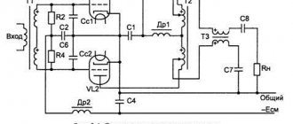
The schematic diagram of the playback amplifier is shown in the figure above (block B1). The circuit is based on the circuit of the playback amplifier of a tape recorder of the highest complexity group “Mayak-010-stereo”.
The playback amplifier is two-stage: the input stage is assembled on a low-noise transistor VT1 (VT1.1 for one channel and VT1.2 for the other), the next one is on operational amplifier A1.
Most playback amplifiers include a coupling capacitor between the head and the input amplifier. It is in this capacitor that the reasons for the increased noise lie, since an electrolytic capacitor always has some leakage current, and therefore is a source of low-frequency noise.
The use of dry capacitors instead of electrolytic ones is not desirable due to the fact that among them there are practically no capacitors with large capacities. And as a result, by reducing noise, we get a frequency-dependent divider at the input, which worsens the frequency response at lower frequencies. This amplifier uses a direct connection of the head to the UV input, eliminating all these disadvantages.
The noise level also depends significantly on the operating mode of the input stage. Therefore, in this circuit, the transistor emitter current is selected to maximize the signal-to-noise ratio when the head is connected and is 40 μA.
Another feature of the amplifier is the use of two independent OOS loops. Temperature stabilization of the operating mode of the output stage is ensured by 100% OOS in terms of voltage (R11, VT2, C8, R12, C4). The amplifier's frequency response is formed by frequency-dependent feedback (R10, C5, R6, R5, R7, R8, R4, SZ). The time constant t2 is determined by the capacitance of capacitor C5 and the resistance of resistor R12. The time constant t1 is set by parameters R9, R5, R7, R8, R4, R6 and C5 and for a tape with a working layer of Fe203 is 120 mkS; when switching to a Cr02 or Met tape, relay contacts K1.1 close
(K2.2), excluding resistor R6, and the time constant is reduced to 70 mkS. The course of the frequency response at higher frequencies is formed by introducing a PIC into the oscillatory circuit formed by the magnetic head and capacitor C2.
The article was “twirled” on many forums in different ways and naturally, everyone everywhere has their own opinion on everything. But we still managed to reduce everything to one thing.
To “bring to mind” the UV, you first need to replace the microcircuit
on LM301A (there are other analogues). Keep in mind that the imported analogues of the UD 2 microcircuit have not 14, but only 8 legs, and accordingly their numbering is different. In UD 2, 1, 2, 7, 8, 13, 14 tabs are not used, and on the boards there are simply contact pads that don’t go anywhere. Replacing capacitors. Electrolytic capacitors through which sound passes (C3, C17, C4, C18, C25, as well as C7, C8 (on early versions of the HC: C3, C18, C4, C20, C27, as well as C6 C8 C13 C14)) are worth replace either with non-polar “audio” or with tantalum K53. You can simply - good, proven ones. In terms of power supply, the containers (C5, C15, C6, C16 (in early versions of the HC: C5, C17, C7, C19)) are simply changed to good ones, tested by time and the tester.
Resistances R19 and R22 are also subject to necessary replacement (on early versions of the HC: R14. R17). there you need to set 330 kOhm. This point was revealed by the respected VANKOR (Ekaterinburg). After replacement, low frequencies sound as they should.
This is where the “modernization” of the hydrocarbons ends. Why is it not worth removing the L1 filter coil and changing the microcircuit that switches playback modes? / reverse on the relay, read below:
Here is what the respected VANKOR (Ekaterinburg) writes about the filter coil (L 1): “This filter plug is needed when, when recording, the tape recorder operates simultaneously in playback mode. Accordingly, the 100 kHz signal is crushed by a parallel circuit, and the bias frequency does not enter the power amplifier path, does not overload it, if it is broadband enough and does not have a destructive effect on the HF speaker. For simple playback, this plug filter is not needed, because 100 kHz is not written on the tape and, accordingly, if this circuit is thrown away and along with it the capacitance that goes to ground at the output, this will slightly increase the slope of the frequency response at high frequencies in the audio range. If you study the circuit, you can see that after the circuit there is still a rather large capacitance C24 paired with a 1 kOhm resistor R46 connected in series, which increases the slope of the frequency response in the HF audio range. The circuit itself does not affect the sound, because set to 100 kHz. If he had influenced, he would not have been installed. Also, if you study the HF circuits of other tape recorders, the filter coil can be found on all devices with a through channel. Conclusion: there is no need to remove the filter plug.”
It is also not worth installing a relay instead of the DD2 microcircuit on early HCs. The microcircuit is based on field-effect transistors and does not introduce noticeable distortion into the sound. And installing a relay can have a very negative impact on the sound over time, because a relay is essentially two mechanical contacts, which are two pieces of metal with a thin layer of oxide on them. An oxide is a dielectric. At “high” voltages, for example, more than 100 millivolts, this micron layer of dielectric breaks through and that’s it... that is. the signal has gone out and we don’t notice anything. But with microVolts, a different situation occurs; the signal may not go through the oxide at all, or it may go through, but with frequency and nonlinear distortions.
To make correction 38, use Revox A700 UV as a sample.
See the HC diagram developed by Konstantin Musatov.
For additions to the topic, write here