Schematic electrical diagrams, connecting devices and pinouts of connectors
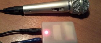
As a result of constant bending of the wire near the 3.5″ Jack plug, noise may appear in the headphones when the connection of the plug to the wire is moved, or even the sound on one of the headphones will disappear completely. Sometimes the common wire breaks, then the sound is distorted: high and mid frequencies disappear almost completely. This happens because the right and left amplifiers of the phone are turned on in antiphase and their output signals almost completely cancel each other out. It also happens that the stereo effect simply disappears. Or there is no sound in the ears, but the microphone works, or vice versa. And sometimes, due to a break in the microphone wire, the control buttons on the headset cord stop working along with the microphone.
If you have such symptoms, we advise you to find a diagram of your plug and re-solder the connector, especially since using these instructions you can do this yourself even without much soldering experience.
So, a TRS type connector is intended for connecting devices, for example, headphones and a player, with each other. The device consists of a plug (plug) and a socket (jack). Often this connector simply breaks at the point where the wires enter the connector itself. Because of this, either the right or left earphone or both at once may not work for you. Moreover, sometimes extraneous noise appears due to wire breaks in the jack 3.5 connector itself.
In general, it is worth noting that the abbreviation TRS itself comes from the English words: tip (tip), ring (ring) and sleeve (sleeve). Among the Russian-speaking population, the concept has been established that “jacks” are the plug itself, so if you use the original name of the TRS connector in everyday life, many will not understand what we are talking about.
Plug types and applications
Depending on the diameter of the working surface, connectors are divided into:
- Micro jack 2.5 mm . They are equipped with small portable devices such as phones, players, etc.
- Mini jack 3.5 . They are installed in household appliances: computers, TVs, etc. In addition, the pinout of jack 3.5 is extremely simple.
- Big jack 6.35 . Mainly used in professional equipment: electric musical instruments, powerful acoustic amplifiers, but can be built into budget equipment, such as karaoke microphones, metal detectors.
Based on the number of outputs (pin), jacks are divided into:
- Two-pin ( TS ). They transmit an asymmetrical signal, for example, a mono signal is sent to headphones or audio is recorded using a microphone.
- Three-pin ( TRS ). Using them, you can transmit both an asymmetrical signal, with pins 2 and 3 connected by a jumper, and a symmetrical one.
- Four-pin ( TRRS ). They can immediately transmit video and audio information. Modern phones, tablets, video players, etc. are mainly equipped with four-pin connectors.
- Five-position ( TRRRS ). An uncommon connector used by Sony in the Xperia Z smartphone for the simultaneous operation of two microphones, one of which works for noise reduction. TRRS compatible.
There are also two types of sockets: regular, created for a specific type of plug, and with a switch - when the pin is inserted, the device switches from one position to another.
Very often there are situations when Chinese collapsible plugs, which were installed instead of a monolithic broken “jack,” do not completely fit into the sleeve or are poorly fixed. Such situations are possible when the diameters of the sleeve and plug do not match. Therefore, when choosing such a plug, it is advisable for you to check its outer diameter with a caliper along the entire working length.
Basic information: how to wire XLR cables and connectors
Modern 3-pin XLR cables are a balanced connector, meaning they have three wires: positive, negative, and ground. In most conventional devices, pin 1 is ground, pin 2 is positive (as specified in AES14-1992, usually called "pin 2 hot"), and pin 3 is negative.
When connecting the connector to the cable, pins 2 and 3 will be connected to the corresponding positive and negative wires, and the cable shield will be connected to pin 1. There are some exceptions to this rule, especially when dealing with some older pieces of equipment, but this is beyond the scope of this article . At least all modern 3-pin XLR cables are always connected to the second "hot" positive pin.
XLR Wiring Guidelines and Notes
In my experience, making and soldering XLR cables is a great option for those just learning to solder. I remember the first time I built one, I was about 16 years old, and I continue to do so to this day. Mainly because I often have to build something to order or repair a damaged cable. All components are relatively large, which makes the soldering process easier for those not yet accustomed to such work, and in the event of an error, replacing damaged connectors is inexpensive.
However, I recommend purchasing a temperature-controlled soldering iron as it reduces the risk of accidentally melting plastic components and ensures there is enough heat to melt the solder. I also recommend using a thinner thickness of solder (I use 0.8mm) because it is easier to work with and melts faster.
Below is a list of everything you need to get started, but this is just an example. You may have other preferences:
- Digital soldering station
- Wire stripping and cutting tools
- Cutter for aluminum, copper, communication cables
- Diagonal cutters
- Round pliers
- Utility knife
- LED lamp with magnifying glass. Magnifier Holder with Alligator Clip - For Soldering
- Lighter
How to find out if the connector is faulty
Insert working headphones into the jack and turn on the music. If music does not play in working headphones, your connector is broken. Also, if you hear a hissing sound when the plug moves, this means that the connector will soon completely fail.
Nowadays, the pinout of headphone wires with a microphone shown in the first picture below is mostly used everywhere, but there is also another one, which is mainly used on old phones and in phones from some manufacturers. They differ in that the microphone and ground contacts are swapped.
Where to insert the microphone on the computer
On the back panel of the computer there are several sockets designed for connecting external devices. They are the same type and are designed for Mini-jac connectors. Externally, the nests differ only in color. To connect a microphone to a PC, use a pink socket with the corresponding icon. Users most often confuse the connection point by inserting a plug into a different socket. This cannot damage the motherboard and external device; it will not work. To avoid problems with finding a “fault,” you need to correctly connect the micro to the desktop. If the external device is working properly, then the settings are reduced to setting the volume and sensitivity. These operations are performed in the “Control Panel” window on the tabs “Sound” - “Recording” - “Microphone” - “Properties” - “Levels”.
Four-wire plug
There are two different options here.
- Ordinary headphones without a microphone and control buttons. 4 wires are connected to the plug: a minus from each copper-colored speaker and a plus (blue with red or green with red). For convenience, the negatives are twisted into one bundle and the result is three wires that need to be soldered to their specific places.
- Headset with microphone. Here the plug has 4 types of contacts: one from each speaker, one for the microphone, and there is room left for soldering a common wire or ground. Schematically, such soldering looks like this:
It should be noted that color marking may vary depending on the imagination of the manufacturer and is very arbitrary. The left channel wire can be green, white or blue. The right channel wire is always marked red. The common wire is copper (varnished or without insulation), but it can also be white if white is not used for the left channel.
Checking the headphone pinout of non-standard connectors
In some mobile devices and GSM phones, in most cases, from previous years of production, phones with original special connectors were used. In such cases, using search engines you can find the original pinout of the headphone connectors. It may have different connection diagrams, for example, shown in the figure.
If the headphones of such devices fail, you can cut the headphone cable, purchase a new headset, and install new headphones in accordance with the diagram.
If there is no information on the Internet, you can independently determine the pinout of the headphones. To do this you need to do the following:
- disassemble the housings of the dynamic headphone system; for this you can use an active solvent;
- ring the terminals of the headphone speakers, zero resistance will correspond to the common wire;
- ring the contacts of the connector with the common wire, the contact number at which the multimeter shows a resistance close to zero will be the contact for connecting the common wire;
- similarly, you should make a call to the opposite contacts of the headphone speakers;
- for a headset with a microphone, search for connections to the connector contacts for each output separately.
Pinout diagrams by manufacturer
Apple audio pinout
- 1 - left
- 2 - right
- 3 - ground
- 4 - microphone
iPod Nano (4th, 5th Gen), iPhone (1st, 2nd, 3rd, 4th Gen), iPod Shuffle (3rd Gen), Cell Phone Connection iPhone headphone (handsfree)
Lenovo audio pinouts
1 - left 2 - right 3 - ground 4 - microphone
Lenovo Thinkpad Edge & X Series Notebook audio
Samsung audio pinouts
1 - left 2 - right 3 - ground 4 - microphone
Samsung Galaxy S I9000, S8500 Wave headset EHS60AVNBE / EHS60ANNWEGSTA / EHS60ANNBECSTD/ GH59-09752A headset Samsung Galaxy S2 i9100 headset should be compatible with Samsung Galaxy Note N7000, Samsung Galaxy Tab GT-P1000, P7100 Galaxy Tab 10.1, 4G LTE, C3530 , [ email protected] 350, Galaxy 551 i5510, Galaxy 550 I5500, E2330, I100 Gem, i220 Code, i350 Intrepid, I9003 Galaxy SL, I9100 Galaxy S II, i997 Infuse 4G, Google/Samsung Nexus S I9023/I9020, [email protected ] 335 S3350, Galaxy mini S5570, Wave 525 S5250, Star II S5260, Wave II S8530, S5780 Wave 578, Wave 533 S5330, Galaxy Gio S5660, Wave 723 S7230, Galaxy Ace S5830, Galaxy Fit S5670, Galaxy S 4G, Galaxy S WiFi 5.0 , R910 Galaxy Indulge, S3850 Corby II, M190 Galaxy S Hoppin, M210S Wave2, M220L Galaxy Neo, M580 Replenish, C6712 Star II DUOS
Samsung i300, i330, i500, i700 handsfree/headset connector
Samsung OEM EHS64 Headset for Samsung Galaxy SIII GT-i9305 and some others
Samsung Series 9 Notebook headset (NP900X3D-A02DE)
Samsung SPH-a420, a580, a640, m220, m240, m300, m320, m330, Rant m540, Exclaim m550 SCH-R451C headset Samsung headset P/N: AEP010SLEB/STD
Samsung SPH-A880, SCH-U620, SCH-U540, SPH-M500, SCH-A950, SCH-A870, SCH-A930, SPH-A920, SPH-A940, SCH-A970, SPH-A900 BLADE, A900M, SCH- A990, SCH-U740 AEP204VBEB/STD Headset/Music
In some Samsung models, the ground contact and microphone can be swapped!
The main reasons for FBK
FBK has not yet been able to establish the exact cause. But most likely it is connected to the spinal cord or brain. Therefore, during diagnosis, the part of the brain that was previously in contact with the remote part of the body (via nerve fibers) is studied.
Some doctors believe that phantom pain manifests itself as a reaction to various signals coming from the brain. Simply put, due to the removal of a part of the body, the brain loses connection with it and is forced to adapt to the new situation. But this adaptation takes an unpredictable path and may be accompanied by the appearance of FBC.
Judging by the research results, the brain is able to redistribute signals from the missing limb to other parts of the body. For example, if there is no hand, then the signal will go to the cheek. And when you touch it, a person will feel as if someone touched his hand.
There are other, but little understood, causes of phantom pain. These are damage to neuron endings, scarring of the remote area and muscle memory. However, some factors can significantly increase the likelihood of unpleasant sensations:
- Pain before amputation: If the patient experienced severe discomfort before the operation, then most likely he will feel it after it.
- Residual pain in the arms or legs due to active growth of nerve endings in the damaged area (neurinoma).
Self-replacement of the 3.5 plug
We will need a knife, soldering iron, solder, rosin. Cut off 5-10 cm of wire from the plug, remove all the insulation from the plug, remember the sequence of wires by color (sometimes they are different). Strip the wires and solder them to the 3.5 mm jack. It is better to fill the soldering area with hot glue and compress it with heat shrink, so the connection will last much longer. Read more about the renovation here
Schematic electrical diagrams, connecting devices and pinouts of connectors
As a result of constant bending of the wire near the 3.5″ Jack plug, noise may appear in the headphones when the connection of the plug to the wire is moved, or even the sound on one of the headphones will disappear completely. Sometimes the common wire breaks, then the sound is distorted: high and mid frequencies disappear almost completely. This happens because the right and left amplifiers of the phone are turned on in antiphase and their output signals almost completely cancel each other out. It also happens that the stereo effect simply disappears. Or there is no sound in the ears, but the microphone works, or vice versa. And sometimes, due to a break in the microphone wire, the control buttons on the headset cord stop working along with the microphone.
If you have such symptoms, we advise you to find a diagram of your plug and re-solder the connector, especially since using these instructions you can do this yourself even without much soldering experience.
So, a TRS type connector is intended for connecting devices, for example, headphones and a player, with each other. The device consists of a plug (plug) and a socket (jack). Often this connector simply breaks at the point where the wires enter the connector itself. Because of this, either the right or left earphone or both at once may not work for you. Moreover, sometimes extraneous noise appears due to wire breaks in the jack 3.5 connector itself.
In general, it is worth noting that the abbreviation TRS itself comes from the English words: tip (tip), ring (ring) and sleeve (sleeve). Among the Russian-speaking population, the concept has been established that “jacks” are the plug itself, so if you use the original name of the TRS connector in everyday life, many will not understand what we are talking about.
Operating principle
There are several principles of microphone operation:
- dynamic;
- condenser;
- carbonic;
- optoacoustic;
- piezoelectric.
But only the first two are common, since the rest are of poor recording quality.
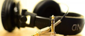
Dynamic microphones include a small electric generator, which consists of a diaphragm - a special plate, a voice coil and magnets. The sound causes the diaphragm and coil to oscillate, and the oscillation causes an alternating current to occur. This type of microphone is reliable and its design allows it to work in a variety of environments. For example, the Audio-Technica ATR-2100-USB dynamic microphone can be used for outdoor press conferences.
Dynamic microphones pick up loud and strong sounds and are almost impossible to overload. Choose them for live performances and concerts.
Condenser microphones work by vibrating a plate with sound. It causes the charge on the capacitor to oscillate, resulting in sound recording. Such microphones are lighter in weight and size, and their sound is more accurate than dynamic ones. Condenser microphones require greenhouse conditions to operate, and the range of processed frequencies is lower than that of dynamic ones. Also, the electronics built into the microphone add noise when recording, which is especially noticeable in cheap models.
Choose them for use in studios, concert halls and theaters.
Microphone with on-camera mount. raylab.ru
Plug types and applications
Depending on the diameter of the working surface, connectors are divided into:
- Micro jack 2.5 mm . They are equipped with small portable devices such as phones, players, etc.
- Mini jack 3.5 . They are installed in household appliances: computers, TVs, etc. In addition, the pinout of jack 3.5 is extremely simple.
- Big jack 6.35 . Mainly used in professional equipment: electric musical instruments, powerful acoustic amplifiers, but can be built into budget equipment, such as karaoke microphones, metal detectors.
Based on the number of outputs (pin), jacks are divided into:
- Two-pin ( TS ). They transmit an asymmetrical signal, for example, a mono signal is sent to headphones or audio is recorded using a microphone.
- Three-pin ( TRS ). Using them, you can transmit both an asymmetrical signal, with pins 2 and 3 connected by a jumper, and a symmetrical one.
- Four-pin ( TRRS ). They can immediately transmit video and audio information. Modern phones, tablets, video players, etc. are mainly equipped with four-pin connectors.
- Five-position ( TRRRS ). An uncommon connector used by Sony in the Xperia Z smartphone for the simultaneous operation of two microphones, one of which works for noise reduction. TRRS compatible.
There are also two types of sockets: regular, created for a specific type of plug, and with a switch - when the pin is inserted, the device switches from one position to another.
Very often there are situations when Chinese collapsible plugs, which were installed instead of a monolithic broken “jack,” do not completely fit into the sleeve or are poorly fixed. Such situations are possible when the diameters of the sleeve and plug do not match. Therefore, when choosing such a plug, it is advisable for you to check its outer diameter with a caliper along the entire working length.
Carbon microphone
Carbon microphone designation on diagrams
The first carbon microphone was invented in America in the nineteenth century by inventor Emil Berliner, on March 4, 1877 to be precise. This microphone is one of the oldest types of microphones. Such microphones were used in telephone handsets, and they did not require an amplifier to operate and could be connected directly to high-impedance headphones.
Photo carbon microphone
Such a microphone consists of a box of carbon powder and a membrane made of metal film, which vibrates under the influence of sound waves. Until someone speaks in front of the microphone, the membrane is stationary, but as soon as you say something, it either bends inward or outward. At the same time, it either compacts or, on the contrary, weakens the pressure on the coal powder; the resistance of the powder, at the same time, also changes, it either increases or decreases. The current in the microphone connection circuit changes accordingly. In the following figure you can see the working principle of a carbon microphone:
Figure - operating principle of a carbon microphone
A carbon microphone has a narrow bandwidth, in other words, it does not reproduce low and high frequencies well and has poor sound quality. Also, the structure of a carbon microphone can be seen in the figure below:
Figure - carbon microphone design
How to find out if the connector is faulty
Insert working headphones into the jack and turn on the music. If music does not play in working headphones, your connector is broken. Also, if you hear a hissing sound when the plug moves, this means that the connector will soon completely fail.
Nowadays, the pinout of headphone wires with a microphone shown in the first picture below is mostly used everywhere, but there is also another one, which is mainly used on old phones and in phones from some manufacturers. They differ in that the microphone and ground contacts are swapped.
Board manufacturing by LUT.
In saying that the boards turn out best when printed on playboy pages. I used to do this, but recently I switched to paper that was glossy on one side. It’s a pity to translate interesting articles into something unknown...
In general, the LUT technology is already known to everyone, and it is shown in the video, so I will focus on only two points.
- I fry it with an iron for a minute, and then throw the board into the nearest book and stand on the book with all my weight for 1-2 minutes.
- I always covered wide areas and transfer or printing defects with a permanent marker. This time I used an acrylic marker instead of a permanent marker. At the same time, I waited 10-15 minutes for it to dry. Nevertheless, he did an excellent job and nothing was poisoned under him.
Four-wire plug
There are two different options here.
- Ordinary headphones without a microphone and control buttons. 4 wires are connected to the plug: a minus from each copper-colored speaker and a plus (blue with red or green with red). For convenience, the negatives are twisted into one bundle and the result is three wires that need to be soldered to their specific places.
- Headset with microphone. Here the plug has 4 types of contacts: one from each speaker, one for the microphone, and there is room left for soldering a common wire or ground. Schematically, such soldering looks like this:
It should be noted that color marking may vary depending on the imagination of the manufacturer and is very arbitrary. The left channel wire can be green, white or blue. The right channel wire is always marked red. The common wire is copper (varnished or without insulation), but it can also be white if white is not used for the left channel.
Step-by-step instructions and stages of making a microphone for a computer
The manufacturing procedure of the device can be divided into several stages.
Schemes and drawings
Before starting work, it is better to sketch out a drawing of the future product. This will make subsequent assembly easier. Since this is a simple option, no specialized programs are needed. The diagram can be made on paper.
Microphone mixer
The mixer is a volume control and amplitude-frequency characteristics. The simplest one can be bought for 3000-4000 rubles. If you don’t want to spend money on it, you can use software mixers (for example, VoiceMeeter Banana or similar software). Their capabilities are not inferior to the functionality of “iron” models.
Rack
If you don’t want to use a buttonhole, you can make a stand to fix the microphone. The easiest option is to make an accessory from an old table lamp. To do this, disconnect the lampshade and attach a metal clamp in its place, the diameter of which allows you to fix the body of a homemade microphone.
The advantage of such a stand is that its position can be changed according to the needs of the owner.
Pinout diagrams by manufacturer
Apple audio pinout
- 1 - left
- 2 - right
- 3 - ground
- 4 - microphone
iPod Nano (4th, 5th Gen), iPhone (1st, 2nd, 3rd, 4th Gen), iPod Shuffle (3rd Gen), Cell Phone Connection iPhone headphone (handsfree)
Lenovo audio pinouts
1 - left 2 - right 3 - ground 4 - microphone
Lenovo Thinkpad Edge & X Series Notebook audio
Samsung audio pinouts
1 - left 2 - right 3 - ground 4 - microphone
Samsung Galaxy S I9000, S8500 Wave headset EHS60AVNBE / EHS60ANNWEGSTA / EHS60ANNBECSTD/ GH59-09752A headset Samsung Galaxy S2 i9100 headset should be compatible with Samsung Galaxy Note N7000, Samsung Galaxy Tab GT-P1000, P7100 Galaxy Tab 10.1, 4G LTE, C3530 , [ email protected] 350, Galaxy 551 i5510, Galaxy 550 I5500, E2330, I100 Gem, i220 Code, i350 Intrepid, I9003 Galaxy SL, I9100 Galaxy S II, i997 Infuse 4G, Google/Samsung Nexus S I9023/I9020, [email protected ] 335 S3350, Galaxy mini S5570, Wave 525 S5250, Star II S5260, Wave II S8530, S5780 Wave 578, Wave 533 S5330, Galaxy Gio S5660, Wave 723 S7230, Galaxy Ace S5830, Galaxy Fit S5670, Galaxy S 4G, Galaxy S WiFi 5.0 , R910 Galaxy Indulge, S3850 Corby II, M190 Galaxy S Hoppin, M210S Wave2, M220L Galaxy Neo, M580 Replenish, C6712 Star II DUOS
Samsung i300, i330, i500, i700 handsfree/headset connector
Samsung OEM EHS64 Headset for Samsung Galaxy SIII GT-i9305 and some others
Samsung Series 9 Notebook headset (NP900X3D-A02DE)
Samsung SPH-a420, a580, a640, m220, m240, m300, m320, m330, Rant m540, Exclaim m550 SCH-R451C headset Samsung headset P/N: AEP010SLEB/STD
Samsung SPH-A880, SCH-U620, SCH-U540, SPH-M500, SCH-A950, SCH-A870, SCH-A930, SPH-A920, SPH-A940, SCH-A970, SPH-A900 BLADE, A900M, SCH- A990, SCH-U740 AEP204VBEB/STD Headset/Music
In some Samsung models, the ground contact and microphone can be swapped!
Self-replacement of the 3.5 plug
We will need a knife, soldering iron, solder, rosin. Cut off 5-10 cm of wire from the plug, remove all the insulation from the plug, remember the sequence of wires by color (sometimes they are different). Strip the wires and solder them to the 3.5 mm jack. It is better to fill the soldering area with hot glue and compress it with heat shrink, so the connection will last much longer. Read more about the renovation here
Health and good mood to everyone! Here I have collected pinout diagrams and instructions on how to solder a plug to headphones of all types known to me. I provide instructions on how to repair headphones with your own hands and how to connect the wires without an electric soldering iron. It will be interesting.
I'll start by listing the known types of audio plugs.
General recommendations
TRS type connectors have a standard pinout. Poor audibility in the headphones may be the result of a break in the common wire or a mismatch between the output impedance of the mobile device amplifier and the impedance of the dynamic headphone system.
TRRS connectors have two types of pinout: CTIA and OMTP. Installing headphones with non-native pinouts leads to distortion of the sound signal and can lead to a malfunction of the microphone.
Topic materials: How to connect wireless headphones to your phone
How to properly set up a headphone microphone on a Windows computer
, How to properly warm up your headphones and whether you need to do it, How to fix your headphones yourself if one stops working, How to improve the sound quality in your headphones, Headphones not working: fault diagnosis, repair methods
, No sound in headphones
, DIY headphone repair
, Making your own simple headphones and headsets with a microphone
There are times when you have to do the pinout of headphones. For example, the device does not work well, and the wire needs to be unsoldered to find the reason.
Standard plugs
According to Wikipedia, there are the following types of jacks:
- TS/TRS 6.3mm diameter (for microphones, electric guitars, mixing consoles, old professional headphones, etc.)
- TS/ TRS / TRRS with a diameter of 3.5 mm (the most common, used for modern headphones, microphones, acoustics, flashes, etc.)
- TS/TRS/TRRS with a diameter of 2.5 mm (for mobile phone headsets, webcams, flashes, etc.)
There is also a type of TRRRS connector, which is used to transmit not only audio, but also video signals.
By the way, this designation is adopted according to the principle: T - Trip (latch), R- Ring (ring), S - Sleeve (sleeve).
How to properly solder a new plug to the headphones, observing the pinout of the wires
To properly solder a headphone or headset plug, you need to know the pinout. It is shown in the table below and taken from the website about connectors.
Minijacks for speakers and microphones also have the same pinouts for 2- and 3-pin plugs.
Plugs and their pinouts for more specialized devices (video cameras, headsets) by manufacturer (Nokia, Samsung, Sony, Panasonic) are shown in the following table.
How does a three-pin jack work?
A regular three-pin stereo jack is designed according to the coaxial principle. Each contact is located in a dielectric sleeve (bushing) and is located inside another sleeve.
The plug contacts are separated from each other by plastic bushings. So this plastic is afraid of overheating, it begins to melt and the contacts will dangle. So if you want to solder a headphone plug, then you should remember about overheating the contacts with a soldering iron.
Marking
The microphone brand is usually marked on its body and consists of letters and numbers. The letters indicate the microphone type:
- MD - reel-to-reel (or "dynamic")
- MDM - dynamic small-sized,
- MM - miniature electrodynamic,
- ML - tape,
- MK - capacitor,
- FEM - electret,
- MPE - piezoelectric.
The numbers indicate the serial number of the development. After the numbers there are letters A, T and B, indicating that the microphone is made in an export version - A, T - tropical, and B - intended for household radio-electronic equipment (REA).
The marking of the MM-5 microphone reflects its design features and consists of six symbols:
- first and second……………MM - miniature microphone;
- third ………………………….. 5 – fifth design;
- fourth and fifth ……….. two digits indicating the standard size;
- sixth …………………………. a letter that characterizes the shape of the acoustic input (O - round hole, C - pipe, B - combined).
In the practice of radio amateurs, several main types of microphones are used: carbon, electrodynamic, electromagnetic, condenser, electret and piezoelectric.
How to repair a headphone plug yourself
To repair a headphone or headset plug with your own hands, you need to carefully remove it from the case if it has not yet fallen out. Usually the plug is filled with rubber. When disassembling, we cut this body along the seam with a sharp knife. The neater the cut, the easier it is to restore the body after repair.
Finding out the cause of the headphones malfunction
The malfunction of headphones most often consists of a break in one of the wires in the plug. Less often, a break occurs near the speaker contacts or the wire breaks due to a violation of the integrity of the insulation.
To determine the malfunction, you need to use a multimeter and ring the plug contacts. From the diagrams above we already know where the common wire and the left and right audio channels are. If the resistance between the contact of one channel and the common wire is more than 20 - 120 Ohms, then most likely there is a break or break in the wire. Remember that the typical winding resistance of modern in-ear headphones is 32 ohms.
The breaking of the wire is determined by the jumping readings of the multimeter when the wire is bent.
The easiest place to find a break is near the headphone speakers. It is often easier to open the speaker housing than to cut the rubber-filled plug. If the wires to the speakers are soldered well, then you should remember about faults in the plug.
Do-it-yourself troubleshooting
Once you have determined the location of the malfunction, you need to get to it and see with your eyes. Then it will become clear how exactly to solder the plug or headphones.
Let's say that a wire break occurs inside the headphone plug. To disassemble the packaged minijack shown above. Ideally, you should record or photograph the wiring and update the connector soldering. Remember that flexible stranded wires are coated with a good varnish and it is difficult to tin them just like that. First you need to burn the varnish, for example with a soldering iron, lighter or mini-burner. After this, you can tin the wires with rosin or other flux.
It is better to leave 2 - 3 mm of bare wire without braiding to increase the strength of the structure. When we return the plug housing to its place or fill a new housing with sealant, it is necessary to create as large a contact area as possible between the braid and the outer sleeve of the plug. Thus, during jerks, the load will be transferred to the most massive part of the plug, and not to the weak contacts of the left and right channels.
After soldering the headphone plug, its internal contacts can be filled with hot melt glue, epoxy glue or sealant. After drying, file to the desired shape.
Microphone amplifier housing
Now a few words about the case. For these purposes, I used a vape case. It had been lying in my closet for a long time, awaiting its fate. It turned out to be just an ideal option, because... has a compartment for the battery and has holes that will be enough for me to be happy.
To begin with, I threw out everything that reminded me of its origin, and also took out and cleaned the contacts for the battery. After that, a switch from a table lamp was installed in place of the button. It was the perfect size; all I had to do was make a cut for the retainer.
In order to minimize the noise level from the preamplifier, I decided to shield the housing. To do this, I cut pieces of copper foil into the removable walls of the case and glued them to double-sided tape. Subsequently, I will connect them to the negative of the battery.
The only thing that bothered me about this case was the hole on the front panel. But it even played into my hands. I cut out an insert from plexiglass, which I glued to the lid. It not only covered the existing hole, but was also designed to demonstrate a blue LED hinting that the device was turned on.
To somehow diversify the insert, and at the same time enhance the glow, I engraved a symbolic image of a microphone on it. Now, even from afar and in bright light, I can always see if my microphone is on.
Well, now all that remains is to thread the wires through the hole and solder them to the board.
How to solder a wire to a headphone speaker
When the wiring breaks near the headphone speaker, it is best to solder it back to the headphone and renew the soldering from the factory. This is how the wires are soldered inside my ancient Aiwa earbuds.
Pay attention to the knot that is tied - it does not allow thin wires to come off when jerking. Before soldering the earphone, be sure to tie the same knot at a certain distance, slightly greater than the distance to the narrow hole.
The question arises - what determines the polarity of connecting the wires to the speaker. The answer is simple - the headphones are connected in the same way so that they work in phase. When the polarity of the headphones is reversed, the sound is smeared and becomes quieter than common-mode sound. If you have a broken wire in one speaker, for proper connection you need to look at the wires and soldering in the other earphone.
What to do if the wire breaks inside the earphone
The most unpleasant thing is when the wire breaks inside the earphone. This means that the speaker winding wire has broken , which is shown in the figure.
The speaker winding is usually glued to the diaphragm and breaks off at the point where the wires are attached to it. Over time, they simply break due to micro-movements.
It is extremely difficult to restore such a break, but it is possible under a microscope. When repairing headphones, you need to be extremely careful not to tear the diaphragm or damage the geometry of the winding. Particular attention should be paid to microdust trapped between the magnet and the winding. Magnetic debris can be easily removed with chewing gum or plasticine.
Sensitivity and frequencies
Microphone sensitivity is expressed in decibels (dB) or millivolts per Pascal (mV/Pa). Negative and low decibel readings mean less sensitivity. A low mV/Pa value also means that the sensitivity is low.
But sensitivity does not equal recording quality, it all depends on what and where you plan to record. For example, at a chamber concert or in a studio interview it is better to use high sensitivity, and on a noisy street - low.
Sound pressure levels, or SPL, are also measured in dB and reflect the maximum sound intensity that a microphone can detect. The average value is 100 dB, high - 130 dB.
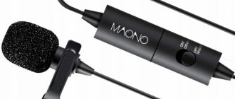
The range of reproduced frequencies determines how natural the sound on the recording will be. Vocals and musical instruments require a range from 40–50 Hz to 15,000 Hz, although 20–30 Hz is recommended for bass instruments. For speech recording, 80–10,000 Hz is sufficient. And for these purposes, the Raylab RecMic SH LavMic wired lavalier microphone, whose range is 20-20,000 Hz, is perfect. This is higher than the recommended average and means that the microphone will not become overloaded during loud sounds. The voice will remain clear even if a car passes by or a helicopter flies in the sky.
High sensitivity microphones are suitable for studios. Photo: rode.com
How to solder headphones with a microphone
To properly repair headphones with a microphone, you need to know the connection circuit and the purpose of the four-pin jack pins. A typical soldering diagram for a microphone plug and a button in a stereo headset is shown in the picture below.
For most manufacturers of simple headsets, the microphone should be soldered as in the picture.
How does a four-pin jack work?
A four-pin jack has the same structure as a three-pin jack. Coaxial design and separation by plastic bushings with standard sizes into 4 wires is present on all TRRS plugs. The pinout of 4-wire plugs differs by manufacturer. There's a lot of people here. To correctly replace the headset plug, look at the pinout of the minijacks in the picture.
The picture shows the following symbols: M - microphone, G - common contact, R - right channel, L - left channel. Now it’s clear that soldering headphones onto 4 wires is not an easy task. The wiring diagram of the plug greatly depends on the brand of the headset.
The nuances of making it yourself
When assembling the system yourself, take into account the following points:
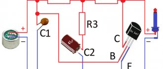
- LM317 stabilizers are used to filter interference. They are used in combination with a 32 V AC voltage source.
- To protect against voltage surges, a zener diode VD2 is built into the circuit. Parameter jumps occur when the capacitor is charged or component R5 is installed incorrectly.
- The reverse voltage should not exceed 35 V. It is also undesirable to use sources that are too weak. Compliance with this rule preserves the range of stabilization and adjustment. To set the required parameters, use element R5.
- The multiplier by 4, necessary to obtain the required voltage, is assembled from components VD1-VD4 and C1-C4. This is followed in the circuit by a double filter consisting of LM317 and R1C5.
- The next step is to install capacitor C7. This prevents the circuit from self-exciting.
- To adjust the output voltage, resistor R5 is used. The device must be powerful because it heats up during operation. The recommended rating is 0.5 W.
About the colors of wires in headphones
Headphone wire colors are usually standardized. The wire colors for standard headphones with 3 wire types are shown in the photo below.
However, there are still manufacturers who use non-standard wires for soldering headphones and marking channels. For example, Apple uses two-color wire markings in its AirPods headphones.
In such cases, the Internet or the method of checking with a 3-volt battery or multimeter comes to the rescue.
When voltage is applied (with a battery or a multimeter in ohmmeter mode) between the contacts of the speaker, a rustling sound will be heard in it. It's simple. It’s more difficult with headsets, especially if they have buttons. This is where circuitry comes into play. Because manufacturers often use a minimum of pairs of wires to transmit a large number of signals.
Board manufacturing by LUT.
In saying that the boards turn out best when printed on playboy pages. I used to do this, but recently I switched to paper that was glossy on one side. It’s a pity to translate interesting articles into something unknown...
In general, the LUT technology is already known to everyone, and it is shown in the video, so I will focus on only two points.
- I fry it with an iron for a minute, and then throw the board into the nearest book and stand on the book with all my weight for 1-2 minutes.
- I always covered wide areas and transfer or printing defects with a permanent marker. This time I used an acrylic marker instead of a permanent marker. At the same time, I waited 10-15 minutes for it to dry. Nevertheless, he did an excellent job and nothing was poisoned under him.
How to do without a soldering iron when repairing headphones
It often happens that a person does not have a soldering iron or socket at hand, and the headphone plug does not work. In this case, we can resolder the plug in several non-standard, but acceptable ways.
The first method is to use conductive glue to glue the wires to the mini jack pins. Everything is done simply and neatly. The reliability of such fastening is of course poor, and the electrical resistance of the glue can be tenths of an ohm. If the headphone impedance is 4 -16 ohms, the glue may affect the sound volume. The good thing is that the drying time for conductive glue is usually 10-15 minutes.
The second method is to heat a nail or piece of copper wire in a candle flame. This is a way for romantics : twilight, candles, plug, headphones and you. In this case, it is better to use scented candles. But seriously, you can solder a headphone plug using a fire and coals. The main thing is not to forget good solder and flux.
The third way is to make a gas soldering iron from a lighter with your own hands. You need to take a piece of single-core copper wire and attach it to the lighter so that part of the wire is in the flame. Heat is transferred over a certain distance through a copper wire, as can be seen from the photo.
If you use this method, pay special attention to the place where the wire adheres to the lighter body. A hole may form there due to heating. Be careful! For more details on how to make such a mini soldering iron from a lighter, watch the video.
History of appearance
The method was developed for land-based telephone exchanges operating on the basis of copper wires. The appearance of phantom power coincides with the creation of disk-based dialers. The method was used to transmit direct current to amplifiers connected to transformers.
The first phantom-powered microphone to go on sale was the Schoeps CMT 20. The model was created taking into account the operating parameters of French radio stations and was introduced in 1964. The company used phantom power until the discontinuation of the Schoeps series. Standard in the 1970s. also used by some Norwegian radio stations.