Subwoofer on 75GDN-1-4
A subwoofer is a low-frequency loudspeaker that reproduces the lowest bass frequencies that are not included in the frequency range of full-range speaker systems working in conjunction with it.
The reason for writing this article was the rather small number of detailed articles on the Internet on ready-made structures. So I decided to make my contribution. For some reason, most of the articles related to car subs - it’s simply amazing how many people we have who are ready to give up half the trunk in order to drive with a roar and jump rhythmically. In addition, noise at speed will still not give pleasure from the sound. My opinion is that you just need to buy good acoustics for your car, that’s usually enough. But at home you can listen to music in a quiet environment and watch a movie with surround sound. The article was intended as a brief summary of the theory with its reflection in practice, so I tried to summarize the theory from other articles - not to invent it myself.
What inspired me to sculpt such a structure? A whole series of events led to this. The DVD generation is coming, everyone around is preoccupied with buying players and discs (fortunately, they now cost $4-6). It was already difficult to stay away, and my long-standing dream of transferring the family archive from a video camera to digital did not give me rest. I sat down on the Internet, studying articles on DVDs, from equipment to creating my own discs, fortunately I already knew how to digitize and process videos. It was decided to wait until the summer, when DVD writers would become a little cheaper, and buy all this newfangled equipment. To begin with, it was decided to assemble everything ourselves in order to get by at the lowest possible cost. The first thing I bought was a DVD player, which was purchased with the intention of testing my DVD film library on a home player. Moreover, I couldn’t wait until the summer. I chose it based on price and capabilities, as well as the fact that I don’t have a receiver and probably won’t have one in the near future, so it had to have a decoder and an output for 6 channels at once. As a result, I bought a BBK-919PS (at that time it still had a Panasonic drive).
I had a pair of S-30 speakers connected to the computer through a homemade computer amplifier, so I used them for the fronts. There was nothing for the rear, so I bought 15AC-315 (small plastic speakers, but they sound very poor in the mid and high range) and the Vega-120 amplifier for a nominal fee. I decided to connect the central channel to the TV, since it can be separately adjusted from the remote control, and the sound there is sufficient to reproduce voices. And if you have a 29″ TV, you can generally do without a central speaker, because there, as a rule, the sound is very decent. Then, of course, I started testing all the channels in films, since I only had a stereo amplifier. And then it turned out that in other channels there is a lot of sound that is not in the front speakers :), and in the sub there are sounds that are not in any of the channels at all. After reading on the Internet about the recommendations of the best saba-kavods, as well as the recommendations of friends who own a house. cinemas, I was obviously fired up.
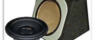
And then a friend advised me to put this together myself, slipped me a couple of articles on 75GDN and recommended that I go to the market and look at the speaker. After much torment and thought, I bought a 75GDN-1-4 on the market for $23, as the cheapest and best described on the Internet, although I looked at different ones, including JBL from $80 to $250 :). I must say, the first thing I did before purchasing was to study the prices. The most affordable price for purchase turned out to be Sven-Audio, but it’s still a bit expensive and the sound quality is questionable. So, the simplest sub would cost $180, and a normal sub would cost about $300-350. All expenses for the production of the subwoofer were recorded, so I have calculated the cost of the design , but first things first...
Theory and measurements of speaker parameters
To calculate the speaker, you need to know at least the basic parameters of the speakers. These parameters are all over the Internet, but the trouble is that they all give implausible parameters for 75GDN-1-4 (I don’t know about others). On one of the sites I found
on this speaker, I trust these parameters more. There are probably reasons for this, one of them is that such heads were produced by a whole bunch of factories and for quite a long time by Soviet industry, so the parameters may have changed over time. But the fact is that, as it turned out, they changed 2 times! And with the parameters from the reference books, when calculated in the program, the volume of the box turned out to be 5 liters, which alerted me. By the way, in almost all the articles I read there were recommendations to measure YOUR speaker parameters. The decision to take the parameters of my speaker was made after a week of fiddling with subwoofer calculation programs (despite the terrible laziness of doing this), in which it turned out that these parameters greatly affect the size of the box and the frequency response, respectively. In order to understand what parameters are needed and what they are used with, as well as how to get them without having any sensible measuring instruments at hand, this chapter will be discussed.
I will write briefly; anyone who wants can read in more detail in the attached literature from which the material was collected.
It may seem strange, but the speaker is mainly characterized by three parameters proposed by Till and Small:
| Fs – resonance frequency in open space; |
| Qts – total quality factor of the speaker; |
| Vas – equivalent volume. |
Fs is the resonance frequency of the speaker without any acoustic design. This is how it is measured - the speaker is suspended in the air at the greatest possible distance from surrounding objects, so that now its resonance will depend only on its own characteristics - the mass of the moving system and the stiffness of the suspension.
Qts is the ratio of the speaker transfer function at frequency Fs to the transfer function at frequencies where the amplitude-frequency response (AFC) of the speaker is horizontal, i.e. at frequencies above Fs. In other words, Qts characterizes the efficiency of the speaker at the resonant frequency.
Vas is the volume of air that has flexibility (the inverse value of elasticity) the same as the moving speaker system. When a speaker is placed in a closed box (CC), the flexibility of the air inside the box adds to the flexibility of the speaker's moving system and its resonant frequency changes. There is the following pattern: when a speaker is placed in a box of volume Vas, its resonant frequency Fs and quality factor Qts increase by 1.4 times.
Measuring these parameters at the first glance at the design is quite a hassle, but having done it once, all doubts disappear - everything turns out to be quite simple. First you need to prepare:
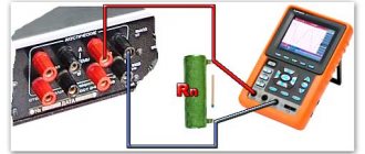
- download the signal generator program for the sound card - you can also merge it - the oscilloscope to the sound card. By connecting the output to the input - you can see what the generator is doing - download my calculation file in Excel - find a 1 kOhm resistor - take a stereo, at least a power amplifier, because you first need to amplify the signal itself, and then the signal being measured - it’s advisable to take a digital voltmeter, Avoid recalculating and clicking ranges. I took the digital one and the pointer one and compared the results to check.
Next you need to assemble the following circuit:
Further:
- Take a pen and paper
- We launch the generator program, set the volume on the computer to the middle (otherwise the sine wave will be cut off), and the rest will be corrected with an amplifier.
- We connect a voltmeter to points A and C (i.e. to the output of the amplifier), and set the voltage to 10-20 V at a frequency of 500-1000 Hz, adjusting the volume on the amplifier.
- We connect the voltmeter to points B and C (i.e. to the speaker).
- We set the generator to ~5Hz and REMOVE the SPEAKER away from all objects and walls (you can hang it up if possible). Practice has shown that, far from objects and on the floor, a speaker lying on the floor still gives different readings, but they are insignificant, but will affect the purity of the experiment.
- By changing the frequency of the generator, we look at the voltmeter readings - we are interested in the maximum and minimum voltage. Approximately near the resonant frequency, the voltage increases sharply, and then drops sharply. At maximum voltage, we look at the frequency - this is Fs.
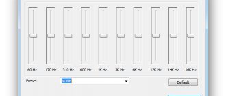
Thus we already have Fs. By changing the frequency upward relative to Fs, we find frequencies at which the voltmeter readings are constant and significantly less than Us (with a further increase in frequency, the voltage will begin to increase again). Let's write down this value, Um. It is better to repeat the procedure with a decrease in frequency. From these records we get something like this graph:
Where, Fs is the resonant frequency, and Us is the corresponding voltage. Um is the minimum voltage, U12 is calculated in Excel after entering the data into the cells. Again we turn the frequency again and look for when the voltmeter readings coincide with the value of U12, remember the frequency. There should be two such values, as can be seen from the graph. These will be F1 and F2. We enter them into Excel. That's it - look at the value of Qts. I made two calculation methods to check the correctness of what I calculated; in the end, the readings agreed, and the small difference is explained by the calculation error. You don’t have to count Vas, but take it from the reference data, it is similar to the truth, and this parameter does not greatly affect the calculation of the box. In addition, to calculate it, you will have to build a plywood box that is sufficiently rigid and airtight, and then repeat the measurements. If you still want to calculate Vas, read the source text on how to do it. I set myself a goal to create something like a summary of the materials that I read, in order to discard the unnecessary, and for an in-depth study of the issue, I provide all the links at the end of the material. So we removed the speaker parameters. For 75GDN-1-4 this is what happened:
| My speaker settings | Reference parameters (from the Internet) | |
| Fs | 34 | 25 |
| Qts | 0,46 | 0,21 |
| Vas | not measured | 80 |
The most important parameter is Qts. How do you feel about the difference? TWICE! I must say that I downloaded about a dozen speaker reference books, other parameters in them fluctuated, but this one was surprisingly stable. So trust people after this...
Let's move on. Now you need to choose the type of box where you can put all this stuff. And this is where the exact speaker parameters come in handy.
There are only three most common types of acoustic design:
| Drawer type | ClosedBox (ZY) Closed | Phase Inverter (FI) Vented | Bandpass (BP) 4th and 6th orders Bandpass |
| Selection criterion | Qts < 0.8-1.0, optimally 0.7 Fs/Qts=50 | Qts<0.6, optimum - 0.39 Fs/Qts=85 | Fs/Qts=105 |
| Distinctive characteristics | This is the easiest type of speaker system to manufacture. Despite the simplicity of the design, it has many advantages, but the C.P.P. is the smallest compared to any other type of acoustic design - as a result, the need for considerable power and possible failure of the speaker (from excessive efforts To calculate the characteristics, there is only one parameter - the volume of the box. | In its operating range, the bass reflex creates completely greenhouse conditions for the speaker, and exactly at the tuning frequency the oscillation amplitude is minimal, and most of the sound is emitted by the tunnel. The permissible input power is maximum here, and the distortion introduced by the speaker is, on the contrary, minimal. The bass reflex is much more capricious in the selection of parameters and settings, since three parameters are subject to selection for a specific speaker: box volume, cross-section and tunnel length. | Efficiency champion. By choosing the appropriate volumes and frequency tuning of the front chamber, it is possible to build a subwoofer with a wide bandwidth but limited output, that is, the bell will be low and wide, or one with a narrow bandwidth and very high efficiency. in this strip. The bandpass is a tricky thing to calculate and the most labor-intensive to manufacture. But the speaker is buried inside - there is less risk of damaging the speaker and there is practically no need for a bandpass filter (although in practice it turned out that it is still desirable) |
the problem - why do I need a column with low efficiency? The speaker is not the most powerful anyway - nominal 50W, maximum 75W. In addition, considerable pressure is created inside the column, which requires special tightness. And the Fs/Qts setting is not suitable for my speaker. True, the ZY is also the smallest box of all - which can sometimes turn out to be important.
FI for three reasons: 1) I need to make a super even hole and then cover it with something, otherwise my child will immediately condemn the speaker 2) I need to install a filter to cut off frequencies above 200 Hz, otherwise the 75GDN will not sound cool at all. 3) normal low-end roll-off was obtained with a wild box size of 120-150 liters (another closet in the apartment), my wife would have kicked me out along with this subwoofer BUT! Fs/Qts=74, i.e. the speaker is most suitable for FI, and at the same time gives cool lows, only SIZE 8(. Here you need to take into account that for single bandpasses almost the same speakers are suitable as for bass reflexes. The bandpass suited me and I liked it the most. There is no need to make a filter - the case itself filters. The speaker is hidden inside - you can’t pierce it. And calculations in the programs showed the best results with the appropriate size...
Calculation and design of the box
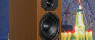
Calculations showed that the Bandpass had relatively good dimensions and a good drop-off at the bottom, however, the drop-off still depended heavily on the volume and we had to make a compromise by slightly reducing the box to 65 liters. I carried out the calculations in three programs at once in order to check the accuracy of what I had built. The results were almost identical. I used WinISD 0.44, WinISD Pro Aplha and or (find 10 differences called). I liked the first program the most, the second was terribly buggy (that’s why it’s Alpha), but in some respects useful, the third simply confirmed my calculations (it has a very inconvenient interface - it’s bad to change parameters on the fly, selecting values for the size of cameras and bass reflexes, and after each boot you need to switch to the metric system). So what happened - look at the graphs (you can take the project files later):
This can be seen in the comparison between BP and FI. With equal box volumes, the FI is significantly inferior to the Bandpass. And for large ones it’s the other way around. So if you want to have a new wardrobe at home, then you should take a closer look at FI. About the hump in the middle, see below. And almost the same in JBL SS:
Here the volume of the FI is slightly smaller, but it is still 2 times larger than the given BP. For PSU, the volume is also critical; you can make it larger, thereby reducing the dip in the middle and improving the roll-off at the bottom.
The calculation comes down to selecting the displacement of the cameras and the frequencies to which they are tuned, and checking the frequency response. I think the other three graphs will not bother you :).
The hole in the middle could not be removed at all - such is the speaker :). I didn’t want to increase the volume, I had to fit into the room, by the way, the box is quite big anyway. But I think such a dip can be neglected - after all, a 3dB dip is very small (the graph is just stretched in height), and if you take into account the uneven frequency response of the speaker itself at 10dB, then you can simply forget about it. In addition, this is still an idealized frequency response, in life everything is much more complicated and confusing. The dip can be made smaller by narrowing the frequency, but I wanted to extend the frequency response to 200Hz, which was not entirely possible, but it certainly got to 150Hz :). I’ll note right away that the middle is still audible in the subwoofer through a thick hole, so an active filter won’t hurt, which I then did in the amplifier.
Calculation of phase inverters comes down to setting the internal diameter of the pipe in meters and checking the “Vent mach” value to green, when it turns red - bad - too much air flow, i.e. this is no longer a subwoofer, but a musical instrument of the “pipe” type. Here you need to look at the length of the bass reflex so that it fits into the box, and preferably up to the middle. For a long time I could not fit the size, because by increasing the diameter, for normal air flow, the length of the phase immediately became immeasurable. The length depends on the diameter and the frequency to which the phase is tuned - so you can also play with the frequency. In this case, the frequency response will change, keep this in mind.
At first, a sub with identical pipes was made, fortunately in the upper one, the program shows less air resistance, but after assembling the 100W amplifier and listening, it turned out that after ~50W the effect of air exhaust (popping) began just in the upper compartment (the smallest one, however) ). I had to disassemble everything and cut a large hole for a thick 105mm pipe inside, so I almost fit right into the height of the camera - 2cm remained. Considering that you also need to fit a sound absorber there, this is a very small margin. I used plastic sewer pipes. Here I note that there are 70mm pipes, but they are not as big as 50mm and 105mm. As the upper phase increased, the lower phase immediately began to work better. I really don’t recommend setting it to 50mm - for such a fool it’s very small. The result is this: for a sub, the dimensions of the elements are the most important.
| First option | Final version |
All the speaker parameters are shown below in the windows, but you can take all this in the project files for both programs: for WinISD and for JBL SpeakerShop.
Well, the volumes have been determined, it’s time to calculate the box and structure. Since I do 3D modeling as part of my job, I did just that - I took the SolidWorks program and created a 3D model there. If you noticed, 3D graphics are also involved in the website design. The program itself calculated the volume for me. It’s difficult to do this yourself accurately, since all the connecting bars in the structure eat up a decent amount of space, and the design had to be invented and changed on the fly. Another problem was the material and its thickness, and the program immediately made it possible to see the dimensions of each element, taking into account, precisely, the thickness of the sheet and the connection with each other, i.e. I automatically got the dimensions of each element.
Separately about the material. Well, I didn’t even think about MDF, although of course the best option. The task was to find 20-22 mm chipboard, but it turned out to be practically impossible. The most common chipboard is 16mm or 18mm laminated Polish. 16mm is not enough, and laminated on both sides is probably bad for sound, and it also turns out to be expensive. Then I realized how right I was by not buying laminated chipboard. And it took about 1.5 weeks to find a regular 18mm one. Those that were in stores are impossible to take home, because the sheet is very large. I have already called all the offices and visited all the markets. My nerves were starting to get the better of me - I almost regretted contacting the sub, because everything except the box material had already been purchased. I started thinking about how to glue 16mm chipboard and 4mm plywood, but I stubbornly didn’t want to glue it - this requires special glue and a strong press. And then a friend called and asked for help to bring cement to his home. So, while we were running around looking for cement and its owners throughout the industrial zone, we accidentally came across an office selling and sawing that very notorious laminated Polish chipboard. They used 22mm chipboard sheets as spacers in the racks. But the owner was not there and we had to wait... Having looked again for the owners of the cement and not finding them, we again returned to the chipboard. The owner did not give me the 22mm, citing the fact that it was difficult to pull out, and they seemed to have already sagged (in short, I was too lazy to pull out) and offered me 28mm. This is cool, I thought, and refused, looking at these thick sheets. And then he offered me 18mm, simple sanded chipboard - it turns out that it is used as transport sheets for laminated (top and bottom). So, all the good stuff, including sawing on an imported machine, cost me $5 (cutting $0.3/m). You won’t be able to cut it like that in real life—evenly, exactly to size. Draw your own conclusions...
Yes, what am I talking about? Oh yes - about the box. Let's see what happened:
As you guessed, this is a 3D model. The length of the bass reflexes is visible in the screenshots of the program above and is 19 cm at the top and 25 cm at the bottom, the internal diameters are 105 mm and 70 mm, respectively. There is a hole in the back wall for the connector socket. The legs were made of steel spikes at the factory and hardened. I chose the size according to my taste. In the articles I found, people made the spikes 2 times larger, but I didn’t want to put the sub too high so that the spikes wouldn’t be visible, because the design is not low anyway. You need 4 spikes, I tried it on 3 stands - it’s a terribly unstable structure. In the columns you can get by with three, since they are not deep and their center of gravity is in the front. I leveled the height of the spikes with a washer; only one was needed, then I checked it on a obviously flat surface (the back wall).
Next, let's look at the stages of assembling the structure...
Assembling the box
I will omit the cutout of the holes in the chipboard, we will assume that they are cut out. I cut everything out with a jigsaw. Without him, I probably would have had a pipe. They are also great for cutting timber, but one bad thing is that it buzzes incredibly.
Stage 1
Assembling the middle and lower shelves. First, I rounded the upper inner edges of the beam. The 20x30mm beam is fastened with 45mm long screws. I pre-drilled holes for the screws everywhere. The entire assembly of wooden units was placed on EXTRA PVA - this is a thicker PVA for stronger gluing. All corners were coated with silicone sealant for wood - it is harder than usual for glass, etc. But I think anyone can do it.
Stage 2
We screw the side walls to the bars from the inside with 35mm screws. The middle shelf must be measured fairly evenly. Don't forget the glue. We attach timber to the side walls at the front. It turns out to be a beam, in front, around the entire perimeter of the large chamber.
Stage 3
We glue the bass reflexes to the front wall. I glued them with liquid metal - such a solid multi-component garbage, it smells like epoxy. She kneads it with her hands, it turns out like plasticine - soft and terribly sticky. It hardens almost instantly as soon as it cools down, and if it doesn’t cool down, it still hardens after 5-10 minutes, so I then removed it from my hands with pumice stone along with the skin . I made a thickening along the entire radius at the base, for reliable fastening - they still stick out far. In addition, I personally was not able to perfectly accurately cut such a hole with a jigsaw, and these unevenness were miraculously sealed with liquid metal.
I wrapped the bass reflexes with window paper tape in 5-7 layers, smoothing everything very tightly. Then I covered them with linoleum with insulation. The thickness of the phases turned out to be about 7 mm.
Stage 4
We screw the front wall to the bars from the inside with 35mm screws.
In the upper part we screw it onto the corners for greater rigidity of the structure. I used plastic furniture ones with a lid.
Stage 5
We install the speaker on the sealant, fasten it with bolts (I don’t remember the size). We coat it well in a circle - you can see the white sealant in the photo. Solder the wires. I attached a block with connectors to the back wall.
Stage 6
Now all this needs to be covered with a sound absorber. There are many material options. I used foamed linoleum with insulation, and then, in the end, thick padding polyester ~2.5-4 cm, which, in addition to pasting, was also fluffed in a large chamber. The linoleum also needs to be glued to the top and back walls. Can be pasted over in several layers. Thick batting is a good thing, but I couldn’t get it.
Stage 7
We put the top cover and the back cover on the sealant, without glue - then you may have to remove them. I fastened them with furniture ties under an internal hexagon - an excellent thing, it fastens very firmly, the main thing is not to tear it off if you tighten it with a drill, like I do. I attached it at the end, here you have to be careful with the chipboard - it can delaminate. For ties, first drill one long hole, and then enlarge the screwed hole with a larger drill. Two ties are at the top in the front wall, the rest are on top of the lid, and the back one is just around the entire perimeter and in the center. You can see how it is attracted by the protruding sealant, but it is attracted well.
In the photographs there is still the first option, with a small upper bass reflex and padding polyester not yet pasted over. Later I covered the bars with linoleum too. This was, so to speak, the first test assembly, in order to listen to whether it would sound or not. Sounded. But so far I only had a 25W amplifier, it was fine for now... Then I dropped the whole thing and began assembling a 100W amplifier; I had to test the design to the maximum possible. And it was not for nothing that I was afraid of a more powerful amplifier - then it turned out that at maximum the upper phase squelched, but the case was sealed the first time - it was not for nothing that I thoroughly sealed all the seams and corners with sealant. I had to disassemble the entire structure, cut out a larger hole and install a thicker pipe. Here I have already completely “insulated” everything with padding polyester. Inside it became soft, white and warm like a snowdrift. What can I say, it sounded quite good - smooth, soft bass. At maximum volume of the amplifier, the speaker begins to jam, but we must take into account that its nominal value is 50W. It's enough for an apartment higher than the roof, especially since it shouldn't be heard in music, just when you cut it - it adds volume to the music and such a solid low sound. In short - good work...
I plan to cover the entire structure with wood-look film. But first, you need to putty and sand the edges - no matter how accurately I didn’t cut it on a machine, no matter how I tried to carefully assemble everything - there is still a total error of 0.5-1mm. That’s why laminated chipboard is still bad, because you have to immediately glue the tape to the end - in short, it will be crooked.
And you can argue about the feasibility of building it yourself, looking at the costs...
Construction cost
| speaker 75GDN-1-4 | $23,32 |
| Chipboard | $5,18 |
| mounting socket (connectors) | $2,33 |
| fasteners (screws) | $3,11 |
| linoleum | $5,39 |
| padding polyester | $3,11 |
| timber | $1,04 |
| the wire | $3,89 |
| pipe 70mm | $2,59 |
| pipe 105mm | $2,59 |
| dye | $5,13 |
| film | $7,77 |
| putty for wood | $1,40 |
| glue Moment | $1,24 |
| PVA glue | $1,30 |
| skin | $3,89 |
| thorns | $2,59 |
| liquid metal | $3,11 |
| platbands | I'm still dreaming about them |
| Total | $78,96 |
It's certainly not $300. But I note that this is an inactive subwoofer. To compare with a purchased one, you need to add here a preamplifier with a tunable filter, a phase shifter and a power amplifier of about 100 W, and you shouldn’t forget about the power supply (possibly the most expensive one in it). Since I decided to build an amplifier for 6 channels at once, I did not bother with building the amplifier into the sub. Still, there is a lot of vibration inside the case, and it’s difficult to combine the tightness of the box with the ventilation of the amplifier. In general, an amplifier is a thankless job - an awful lot of trouble. I probably won’t show such heroism again. A separate article will be written about the results of designing an amplifier based on the TDA7294...
Article taken from pavel.artmech.com
Tags:
- Subwoofer
Description of work
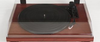
Structurally, the speaker (Fig. 1) is made in the form of three one-piece boxes, rigidly fastened to each other: low-frequency (LF), mid-frequency (MF) and high-frequency (HF). a 75GDN-1-4 loudspeaker head , the second one has a 5GDSh-5-4 and the third one has a 6GDV-4-8 . The location of the boxes relative to each other and their dimensions are selected taking into account the requirements for the radiation pattern and uneven frequency response of the speakers. The drawings of the speakers are not to scale.
And so, for the upgrade we need:
Clone Naim NAP 200 black
Important!
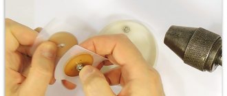
There must be a hole in the core of the speakers to remove the under-dome pressure (it is available in the speakers 75GDN-3, and some later 75GDN-1, including with the index - L), if it is not there, it must be drilled with a drill with a diameter of 15 up to 18 mm. It is better to do this on a drilling machine. For the same reason, cobalt 30GD-1 / 75GDN-1 are not suitable, because their magnet itself is a core, and it cannot be drilled.
I live in Ukraine, so I bought components for the speaker. At the end of the article I will provide approximate prices for all spare parts. In Russia or Belarus, such components can be easily found at auctions or ad sites.
Rice. 5
The low-frequency head is “acoustically suspended”, i.e. installed on the front panel through a ring made of microporous rubber 5 mm thick. The head is secured with M6 screws. The front panel itself is attached to wooden blocks installed on the side and bottom panels with M6 screws. The joints between the panels are carefully coated with sealant from the inside. The bass reflex pipe is made of duralumin with a wall thickness of 1 mm. It is glued into the front panel with PVA glue. On the outside of the pipe there is a decorative ring machined from plywood. The rear panel of the woofer box is secured through 2.5 mm thick foam rubber with 24 screws with a diameter of 4 and a length of 45 mm.
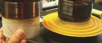
The separating filter elements are placed on a fiberglass board, which is installed on the bottom panel through rubber gaskets. The filter uses PEV-2 resistors and MBGO capacitors for a voltage of 160 V. Coil L1 contains 172 turns of PEV-1 wire Ø1.8, L2 - 90 and L4 - 78 turns of PEV-1 wire Ø1.2 and L3 - 186 turns of PEV wire -1 Ø1.62. The winding diameter of the coils L1—L4 is Ø56, Ø28, Ø52 and Ø25 mm, respectively, the winding height is 28 mm, 14 mm, 26 mm and 12.5 mm. Cotton mats measuring 70x400x250 mm are fixed to the inner surfaces of the side, rear and top panels. There are two mats on the side panels, and one on the top and back panels. Two side rails measuring 20x20x300 mm are attached to the bottom panel from the outside using PVA and screws; they serve as speaker stands. The side surfaces of all three boxes and the front panel of the woofer box are covered with black leatherette.
Article for Competition No. 4 “Tell about Your Sound”
As is known, standard speakers 75GDN-1, partially 75GDN-3, as well as 75GDN-2 and 75GDN-6, despite their great popularity, have shortcomings in sound, which are associated with the large weight of the moving speaker system and a large dust cap.
These disadvantages are that the above speakers cannot reproduce live drums well, especially if the drums are “fast”. You can often find information on forums that if such speakers are replaced with polyurethane foam or a fabric surround, the sound changes for the better, but I am convinced that it is impossible to install a very soft suspension on a heavy moving system.
It is clear that a lighter suspension will give a slight increase in sensitivity, but at the same time, the resonance of the moving system will decrease, and thus a head with a foam/fabric suspension and still a heavy feat will be even more unable to play the attack of the drums. Even if you try to increase the resonance of the head, for example, by installing two center washers, the pulse characteristics of the head will certainly improve, the overall quality factor will drop, but at the same time, the sensitivity will also drop, and as you know, with standard 75GDN it is not high - 86 dB/W* m.
Through trial and error, I found a way to dramatically change the sound of the 75GDN heads, make the bass lighter, airier, faster, and at the same time even increase sensitivity and, not only that, reduce the level of distortion. This method consists of replacing the standard moving system with a new one with a Kevlar diffuser. Kevlar is known to have excellent properties, which makes it possible to use this material for the manufacture of high-quality woofers. Kevlar is highly durable, resistant to deformation, high temperatures and moisture, and at the same time has a very beautiful appearance.
Rice. 2
The filter crossover frequencies of 500 and 5000 Hz were selected to ensure minimal unevenness in the frequency response of the speakers. For better coordination with the LF and HF heads, the midrange head is turned on in antiphase with them. This design of the crossover filter best suits the characteristics of the loudspeaker heads used in the speakers and their acoustic design. The housing of the HF unit (Fig. 1) is assembled from blanks (Fig. 3) made of chipboard 16 mm thick (1, 4 and 5) and plywood (2) 10 mm thick.