When designing the circuit of my low-frequency amplifier, I included in it a speaker protection unit in advance. Why is this needed and what can harm speaker systems? — firstly, I wanted to get rid of the “click” when power is supplied to the amplifier.
When the power is turned on, the rectifier capacitors begin to charge, which at this moment affects the ULF - the speaker systems are briefly exposed to constant voltage. To avoid this hit, you need a simple time relay circuit that will delay the connection of speaker systems by 0.5-1 second.
Secondly, anything can happen to the ULF, for example, one of the transistors in the ULF can burn out from an overload and a constant voltage of a sufficiently large value will be supplied to the speakers, which can burn the low-frequency dynamic head or damage part of the filter of your speakers. To eliminate such incidents, you need a circuit that controls the voltage at the ULF output and, in case of problems, disconnects the speaker systems from the ULF.
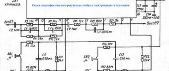
Protection and turn-on delay circuit on four transistors
The above device is designed to delay the connection of loudspeakers for the duration of transient processes in the UMZCH when turning on the power and turning them off when a constant voltage of any polarity appears at its output.
Rice. 1. Schematic diagram of the device for protecting acoustic systems and switching delay, made on four transistors.
The schematic diagram of the device is shown in Fig. 1. It consists of a diode distributor (VD1 - VD6) and an electronic relay on transistors VT1 - VT4.
It is connected to the outputs of the UMZCH channels together with the loudspeakers through the contacts of relay K1. Circuits R1C1, R2C2 prevent the device from triggering audio frequency fluctuations.
If necessary, the number of controlled channels can be increased by simply connecting the corresponding number of additional circuits, similar to the circuit R1C1VD1VD2, and using an electromagnetic relay with a large number of contact groups. The constant voltage at the output of the UMZCH, at which the protection device is triggered, is determined by the voltage of the stabilizer diode VD7 and is related to it by the relation:
When the power is turned on (the voltage source can be the UMZCH power supply), capacitor C3 begins to charge (through resistor R9), so transistor VT4 is closed and relay K1 is de-energized.
As charging occurs, the voltage on the capacitor increases, transistor VT4 begins to open, and after a while (about 3 s) its emitter current increases so much that relay K1 is activated and connects the speakers to the output of the UMZCH.
Transistors VT1 – VT3 are also closed in the initial state. When a voltage of any polarity exceeding the above value appears at the output of any of the channels, transistor VT2 opens, followed by VT1, VT3. As a result, capacitor C3 is discharged through the emitter-collector section of transistor VT3 and resistor R8, transistor VT4 closes and relay K1 disconnects the speakers and the device input from the UMZCH output.
Transistor VT1, which provides positive feedback in the cascade on transistor VT2, plays the role of a “latch”, maintaining the latter in the open state even after disconnecting the device from the output of the UMZCH: without it, after the loss of voltage at the input and closing of transistor VT2, VT3 would start again charging capacitor C3 and after the charging time has elapsed, the speakers would be connected to the UMZCH again.
The device uses a RES-9 relay (passport RS4.524.200). Transistors KT603b (VT3,VT4) can be replaced with KT315g. A 20V power source is used to power the device.
At high voltages, due to reverse collector currents, spontaneous opening of transistors VT1, VT2 is possible. To prevent this from happening, it is necessary to reduce the resistance of resistors R5, R6. If the supply voltage is more than 30 V, the device should use transistors with a permissible collector-emitter voltage of at least.
When reducing the voltage (by replacing the D814a zener diode), care must be taken to ensure that the amplitude of the low-frequency alternating voltage at the outputs of filters R1C1, R2C2 does not reach values that cause the speakers to turn off. This is not difficult to do - just increase the time constants of the named circuits (for example, increase C1, C2).
Improved protection scheme for speakers
The protection device Fig. 2 has great capabilities.
Rice. 2. Schematic diagram of the protection of speaker systems from output voltage surges, powered by the UMZCH power supply.
It protects the speakers from output voltage surges both when turning the power on and off, in the event of a malfunction of the UMZCH and in moments of probable failure of the latter - when one or both supply voltages decrease or completely disappear, as well as when they exceed the maximum permissible values (this may have place when powered from stabilized sources) and, finally, turns them off when connecting stereo headphones. The device is powered from the same two-field source as the output stages of the UMZCH.
At the moment the power is turned on, capacitor C3 begins to charge, so transistor VT2 is open, VT3 is closed, relay K1 is de-energized and the speakers are turned off. As soon as the voltage across the capacitor reaches
- stabilization voltage of the zener diode VD9), the states of the indicated transistors are reversed, relay K1 is activated and the loudspeaker is connected to the outputs of the UMZCH channels.
Connection delay time:
The above formula is valid provided: .
Delay time at the element ratings indicated on the diagram: .
The stabilization voltage of the zener diode VD11 is selected from the condition.
When the voltage of any power source decreases by an amount greater than the transistor VT3 closes and relay K1 disconnects the speakers from the UMZCH.
Zener diodes VD7 and VD9 in the base circuits of transistors VT1, VT2, respectively, are the same and are selected taking into account the following. As can be seen from the diagram, in order for transistor VT2 to open (and therefore transistor VT3 to close and release relay K1), the supply voltage must satisfy the condition:
, where and are, respectively, the voltage and minimum stabilization current of the zener diode VD9.
From here: . With the ratings and types of parts indicated in the diagram
, which means that the device will turn off the speakers if the negative supply voltage increases (relative to the nominal) by 2.8 V.
Transistor VT1 opens along the circuit VD1 - R5 - VD7, identical to the circuit VD6 - R7 - VD9. This leads to the opening of transistor VT2 and the closing of transistor VT3, i.e. to turn off the speakers when the supply voltage of positive polarity increases by 8 V.
If a constant positive voltage appears at the output of the UMZCH, transistor VT2 opens with current flowing through resistor R3 (or R4), VD4 (VD5) and circuit R7VD9. The condition for opening it in this case looks like this:
If the voltage at the output of the UMZCH has a negative polarity, transistor VT1 opens through the circuit R3 (R4) - VD2 (VD3) - R5 - VD7.
To connect stereo telephones, use the XS1 socket, to which the SA1 switch is mechanically connected. When the stereo telephone plug is inserted into the socket, the switch contacts open, relay K1 releases and the speakers are disconnected from the UMZCH.
The same thing happens when you turn off the power to the UMZCH with the SB1 button (A1 is the power source). Since the collector circuit of transistor VT3 and the mains supply circuit are broken almost simultaneously, the speakers are turned off before the transition process begins and a click is not heard.
The device uses a RES-22 relay (RF passport-4.500.130). Non-polar oxide capacitors C1, C2 - K50-6. The KT815V transistor can be replaced by any other with a permissible collector-emitter voltage of more than 50 V and a maximum collector current of at least , where - is the resistance of the relay winding K1).
Instead of KS527A zener diodes, you can use KS482A, KS510A, KS512A, KS175Zh, KS182Zh, KS191Zh, etc., connecting the required number of devices to obtain the stabilization voltage selected by the above formulas. Diodes VD1 - VD6, VD8, VD10, VD12 - any low-power silicon with a reverse voltage of more than 50 V.
↑ Contents of the set
Rice.
1. Whale composition
The whale includes:
• double-sided printed circuit board measuring 65x40 mm, • 7812CT stabilizer chip for 12 V voltage, • six SS8050 transistors, • DB107 diode bridge rectifier, • 1N4148 diode, • red LED d=3 mm, • two SRU-12VDC electromagnetic relays -SL-C, • four oxide capacitors 100 uF x 35 V, • five resistors with a power of 0.25 W (6.8 kOhm, 100 kOhm, 15 kOhm - 3 pcs.), • five two-pin terminal blocks 2 pin with a distance between the pins 5 mm. The set comes with instructions containing a drawing with the placement of parts and text in simple and understandable Chinese. ?
The parts installed on the printed circuit board are signed using silk-screen printing, so the inscriptions on the board and the attached instructions are quite enough to solder the elements (Fig. 2).
Rice. 2.
Double Sided PCB Kit
However, assembling a device without a circuit diagram does not provide an understanding of the principle of its operation and does not bring satisfaction from the result obtained.
AC protection circuit which is powered by the AF signal
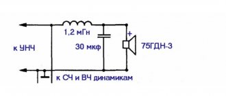
The original loudspeaker protection devices (Fig. 3) are powered by audio frequency signal voltage, which allows it to be built into a loudspeaker.
The device turns off the latter in case of power overload, as well as in the event of a constant voltage of any polarity appearing at the output of the UMZCH. The circuit uses speakers with a power of 10 W and an electrical resistance of 4 Ohms.
Rice. 3. Schematic diagram of the protection of an acoustic speaker, which is powered by an AF signal.
In the initial state, relay K1 is de-energized and the AF (audio frequency) signal from the amplifier output is supplied through contacts K1.1 to the loudspeaker. At the same time, it rectifies with a bridge VD1 - VD4, and its constant component is supplied through normally closed contacts K1.2 to a threshold device made on transistor VT1 and microcircuit DA1.
As long as the input signal voltage does not exceed the operating threshold, the transistor is closed and the voltage at pin 12 of the DA1 microcircuit is equal to the stabilization voltage of the zener diode VD6, which is greater than the voltage of the standard source of the microcircuit, which can be in the range of 1.5 ... 3 V. (The zener diode VD6 prevents breakdown of the emitter junction transistor of the differential stage of the microcircuit with reverse voltage).
At the moment when the input signal reaches the device response level (the voltage on the motor of the trimming resistor R5 is about 1.5 V), the transistor VT1 opens and the voltage at pin 12 of the DA1 microcircuit becomes less than the standard one.
As a result, the control transistor of the microcircuit opens, relay K1 is activated and the loudspeaker is disconnected from the UMZCH, and the relay winding is connected directly to the output of the rectifier bridge VD1 - VD4.
When the rectified voltage decreases to the relay lowering voltage, the device returns to its original state. The device behaves similarly when a constant voltage appears at the output of the UMZCH.
The response threshold is set by trimming resistor R6. Capacitor C3 prevents the device from triggering when the signal briefly exceeds the trigger threshold.
The minimum signal voltage at which the device is operational is determined by the relay response voltage. In the case of using the RES-47 relay (passport RF4.500.407-04) and parts with the ratings indicated in the diagram, it does not exceed 5 V. The VD8 zener diode limits the voltage on the relay winding.
In the absence of the K142EN1A microcircuit, you can use K142EN1, K142EN2 with any letter index. KD522B diodes can be replaced by any other with a reverse voltage of more than 40 V, forward current of at least 100 mA and maximum frequency (KD51A, diode assemblies of the K542 series, etc.), KS107A stabistor - with any silicon diode, KT3412B transistor - with any low-power silicon transistor npn structures with a permissible collector-emitter voltage of at least 40 V.
When manufacturing a device to protect loudspeakers of powerful sound-reproducing devices, you should use diodes KD204A - KD204V, KD212A, KD212B, KD213A, KD213B, etc., replace the RES-47 relay with another one, with contacts that allow switching high currents, and if necessary, “ “power up” the DA1 microcircuit of external transistors to provide the required current through the relay winding.
It may happen that when the device is triggered, the relay contacts will bounce. It can be prevented by connecting a capacitor with a capacity of 10...20 μF between pins 16 and 8 of the DA1 microcircuit or a resistor with a resistance of 1 kOhm between its pin 13 and the base of the transistor VT1 (thus creating a positive feedback).
Speaker protection circuit using a resistor-optocoupler
The proposed device (Fig. 4)
Rice. 4. Schematic diagram of the protection of acoustic systems using a resistor optocoupler.
provides protection for acoustic systems (AS) from damage when a constant voltage of positive or negative polarity appears at the outputs of a stereo amplifier.
The functions of the actuator protection element are performed by resistor optocoupler U1. It works as follows. When a negative or positive DC voltage appears on any of the output audio amplifiers (AUS), the input current begins to flow through the opron and the resistance of its resistor sharply decreases.
As soon as the DC voltage reaches 3-4 V (depending on the type of optocoupler), the resistance becomes so small that transistors VT1, VT2 close, relay winding K1 is de-energized and its contacts K1.1, K1.2 disconnect the speaker from the ultrasonic sounder.
Zener diodes VD1, VD2 limit the input current of the optocoupler to 18 mA. Since for D815A zener diodes a stabilization voltage variation of 15% is allowed, it is necessary to select such specimens so that the voltage applied to the optocoupler light emitter does not exceed 5.5 V.
Chokes L1, L2 limit the alternating component of the input current of the optocoupler to a value that excludes the possibility of protection operation. They are made on magnetic cores ШЛ12*12 and contain 1200 turns of PEL-0.23 wire. the active resistance of each inductor is 36 Ohms.
Due to the long charging time of capacitor C1 through resistor R1, there is a delay in the opening of transistors VT1, VT2, the operation of relay K1 and the connection of the speaker to the amplifier.
As a result of transient processes that occur in the amplifier after it is turned on, they fade out before the device connects the speakers, so a click is not heard in them.
When the amplifier is turned on by switch 8B1, contacts 1 and 4 of the latter close, causing instantaneous closing of transistors VT1, VT2. Naturally, the speaker opens from the amplifier before the start of transient processes in it, and the click in the speaker will also not be heard.
The AC protection device is powered by a 2-pole power amplifier power supply. When selecting elements VT1, VT2, C1, R2, K1, the source voltage should be taken into account.
The copy made by the author uses the RSM-1 relay, passport Yu-171.81.37. You can use another relay suitable for voltage and operating current (it should not exceed 100 mA).
When using relays RES-9, RES-22, the protection device can be supplemented with an alarm system for its operation. (Fig. 5)
Rice. 5. Scheme of supplementing the AC protection device with a light alarm.
The described device was developed for a specific amplifier with a supply voltage equal to plus or minus 15 V. In this case, when the maximum voltage appears at one of the amplifier outputs, the thermal power generated at the chokes L1 or L2 does not exceed 3 W, which eliminates its significant overheating during the time during which a conclusion can be made about a malfunction of the power amplifier (PA) and a decision can be made to turn it off.
↑ Board assembly
The power of the soldering iron should be no more than 25...30 W.
Soldering is easier to do with solder with POS61M rosin. Liquid flux for radio installation work is also welcome. It is important not to overdo it and not allow it to flow under the housings of the elements. You should remember not to overheat the elements. The soldering time for one contact should not exceed 3 s.
Form the resistor leads and install them on the PCB. Solder electrolytic capacitors, observing polarity. Install semiconductor elements (transistors, diode, diode bridge, voltage stabilizer chip). When the inscriptions on the board are located towards themselves, the serial numbers of transistors VT1...VT6 are as follows: VT2, VT1; VT4, VT3 and VT6, VT5.
After soldering is completed, check the installation, paying special attention to the correct installation of polar electrolytic capacitors, transistors, stabilizer chip, diode and rectifier bridge. Check the quality of the rations and correct flaws, if any. The appearance of the assembled board is shown at the beginning of the article.
The second version of the protection circuit with optocoupler
With a higher supply voltage and no guarantee of timely detection of the moment of operation of the protection device, it can be assembled according to a slightly modified circuit (Fig. 6).
Rice. 6. Schematic diagram of the speaker protection device, powered from -30 +30V.
In this case, when the protection system is triggered, the power to the power amplifier is turned off. The light emitter of the optocoupler is connected to the power supply of the amplifier by contacts K1.3 of relay K1, which allows you to keep the protection device in the “Emergency” mode.
In addition, if one of the voltages of the 2-polar power supply is missing, the protection device does not connect the PA to it and turns it off if one of these voltages disappears. Lighting of the LEDs indicates a malfunction in the amplifier or power supply.
In a device assembled according to the diagram in Fig. 3, relay K1 must have 4 groups of contacts for switching (RES-22, passport RF4.500.130). It should be noted that such a protection system scheme loses the function of preventing clicks in the speakers.
↑ Additions from readers
10/17/2021
Comrade Dmitry (
Aknodik
) repeated the design with minor variations. I applied power to the protection unit from the UMZCH transformer.
The original print has been preserved, a diode bridge D6-D9 and a filter C5 have been added. The board receives power from the secondary of the amplifier transformer. D6 - D9 = FR102-FR107; 4007, etc. Select diodes according to Urev, and I >= 200mA. C5 = 4.7-10uF, slave. the voltage depends on the power supply, set it to 50V, you can’t go wrong. On the signet there is a connector for the wires from the transformer, but I didn’t install it, I regretted it. I didn’t make any adjustments, the unit starts up and works right away.