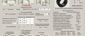
To obtain a full-fledged low-frequency power amplifier, a good power source is required; a diagram of a simple power supply for an UMZCH is shown. The sound quality depends almost as much on the parameters of the power source as on the amplifier itself, and you should not be negligent in its manufacture.
There are more than enough descriptions of calculation methods for standard transformers. Therefore, here we offer a description of a switching power supply that can be used both with amplifiers based on the TDA7293 (TDA7294), and with any other AF power amplifier, both on microcircuits and on transistors.
The basis of this power supply unit (PSU) is a half-bridge driver with an internal oscillator IR2153 (IR2155), designed to control MOSFET and IGBT technology transistors in switching power supplies.
Schematic diagram
The functional diagram of the microcircuits is shown in Figure 1, the dependence of the output frequency on the ratings of the RC master chain is shown in Figure 2.
The microcircuit provides a pause between the pulses of the “upper” and “lower” switches for 10% of the pulse duration, which makes it possible not to worry about “through” currents in the power part of the converter.
Rice. 1. Functional diagram of microcircuits IR2153, IR2155.
The practical implementation of the power supply is shown in Figure 3. Using this circuit, you can make a power supply with a power from 100 to 500 W, you only need to proportionally increase the capacitance of the primary power filter capacitor C2 and use the corresponding power transformer TV2.
Rice. 2. Graphs of the dependence of the output frequency on the ratings of the RC-drive chain for the IR2153 microcircuit.
The capacitance of capacitor C2 is selected at the rate of 1... 1.5 µF per 1 W of output power, for example, when manufacturing a 150 W power supply, a capacitor of 150... 220 µF should be used.
Rice. 3. Schematic diagram of a switching mains power supply for 100-500W low-frequency amplifiers.
The VD primary power supply diode bridge can be used in accordance with the installed primary power supply filter capacitor; with capacitances up to 330 µF, 4...6A diode bridges can be used, for example RS407 or RS607.
With a capacitor capacity of 470... 680 µF, more powerful diode bridges are needed, for example RS807, RS1007.
Mains voltage rectifier: the most popular design
Rule No. 3: after the output from the filter, the voltage is supplied to the rectifier circuit , which in the basic version consists of a diode bridge and an electrolytic capacitor.
During the electrical conversion, the shape of a sine wave, consisting of half-waves of opposite signs, first changes to a signal in a positive direction after the diode assembly, and then these pulsations are smoothed out to an almost constant amplitude value of 311 volts.
Such a network voltage rectifier is included in the operation of all power supplies.
About the transformer
We can talk about the manufacture of a transformer for a long time, but not everyone needs to delve into the deep theory of calculations for too long.
Therefore, calculations according to Eranosyan’s book for the most popular standard sizes of ferrite rings M2000NM1 are simply summarized in Table 1.
Table 1. Overall power of the transformer at different conversion frequencies, number of turns for the primary winding.
| type | 40kHz | 50kHz | 60kHz | 70kHz | 80kHz | 90kHz | 100kHz | ||
| FOR RING K40x25x11 | |||||||||
| 1 RING | K40x25x11 | power | 100 | 130 | 160 | 175 | 200 | 220 | 250 |
| turns | 180 | 145 | 120 | 105 | 90 | 80 | 72 | ||
| 2 RINGS | K40x25x22 | power | 200 | 230 | 280 | 330 | 370 | 420 | 470 |
| turns | 90 | 72 | 60 | 52 | 45 | 40 | 36 | ||
| FOR RING K45x28x8 | |||||||||
| 1 RING | К45х28х8 | power | 110 | 135 | 150 | 180 | 200 | 230 | 240 |
| turns | 217 | 174 | 145 | 124 | 110 | 97 | 87 | ||
| 2 RINGS | К45х28х16 | power | 200 | 240 | 290 | 340 | 390 | 440 | 480 |
| turns | 109 | 87 | 73 | 62 | 55 | 49 | 44 | ||
| 3 RINGS | K45x28x24 | power | 290 | 360 | 440 | 510 | 580 | 660 | 730 |
| turns | 82 | 66 | 55 | 47 | 41 | 36 | 33 | ||
| 4 RINGS | К45х28х32 | power | 380 | 490 | 580 | 680 | 780 | 870 | 970 |
| turns | 62 | 50 | 41 | 35 | 31 | 28 | 25 | ||
| 5 RINGS | К45х28х40 | power | 500 | 600 | 700 | 850 | 950 | 1100 | 1200 |
| turns | 50 | 40 | 35 | 30 | 25 | 22 | 20 | ||
| 6 RINGS | К45х28х48 | power | 550 | 700 | 850 | 1000 | 1150 | 1300 | 1450 |
| turns | 41 | 33 | 28 | 24 | 21 | 19 | 17 | ||
| 7 RINGS | К45х28х56 | power | 650 | 850 | 1000 | 1150 | 1350 | 1500 | 1700 |
| turns | 35 | 30 | 24 | 20 | 18 | 16 | 14 | ||
| 8 RINGS | К45х28х64 | power | 750 | 950 | 1150 | 1350 | 1550 | 1750 | 1950 |
| turns | 31 | 25 | 21 | 18 | 16 | 14 | 13 | ||
| 9 RINGS | К45х28х72 | power | 850 | 1000 | 1300 | 1500 | 1750 | 1950 | 2200 |
| turns | 28 | 22 | 18 | 16 | 14 | 13 | 11 | ||
| 10 RINGS | К45х28х80 | power | 970 | 1200 | 1450 | 1700 | 1950 | 2200 | 2400 |
| turns | 25 | 20 | 17 | 14 | 12 | 11 | 10 | ||
As can be seen from the table, the overall power of a transformer depends not only on the dimensions of the core, but also on the conversion frequency.
It is not very logical to make a transformer for frequencies below 40 kHz - harmonics can create insurmountable interference in the audio range. The manufacture of transformers for frequencies above 100 kHz is no longer permissible due to self-heating of the M2000NM1 ferrite by eddy currents.
The table shows data on the primary windings , from which the turns/volt ratios can be easily calculated, and then it will not be difficult to calculate how many turns are needed for a particular output voltage .
XLS table, to help with calculations (change only yellow cells) - .
It should be noted that the voltage supplied to the primary winding is 155 V - the mains voltage of 220 V after the rectifier and smoothing filter will be 310 V DC, the circuit is semi-bridged, therefore half of this value will be applied to the primary winding.
It should also be remembered that the shape of the output voltage will be rectangular, therefore, after the rectifier and smoothing filter, the voltage value will not differ significantly from the calculated one.
The table is shown up to powers of 2400 W (for the future, for more powerful power supply circuit options).
The diameters of the required wires are calculated from a ratio of 5 A per 1 sq mm of wire cross-section. Moreover, it is better to use several wires of smaller diameter than one, thicker wire.
This requirement applies to all voltage converters with a conversion frequency above 10 kHz, since the skin effect is already beginning to affect itself - losses inside the conductor, since at high frequencies the current no longer flows across the entire cross-section, but along the surface of the conductor, and the higher the frequency, the Losses in thick conductors have a stronger effect.
Therefore, it is not recommended to use conductors thicker than 1 mm in converters with conversion frequencies above 30 kHz. You should also pay attention to the phasing of the windings - incorrectly phasing windings can either damage the power switches or reduce the efficiency of the converter.
About power supply unit and transients
But let’s return to the power supply shown in Figure 3. The minimum power of this power supply is practically unlimited, so you can make a power supply with 50 W or less. The upper power limit is limited by certain features of the element base.
To obtain higher powers, more powerful MOSFET transistors are required, and the more powerful the transistor, the greater the capacitance of its gate.
If the gate capacitance of the power transistor is quite high, then a significant current is required to charge and discharge it. The current of the IR2153 control transistors is quite small (200 mA), therefore, this microcircuit cannot control too powerful power transistors at high conversion frequencies.
Based on the above, it becomes clear that the maximum output power of a converter based on IR2153 cannot be more than 500...600 W at a conversion frequency of 50...70 kHz, since the use of more powerful power transistors at these frequencies quite seriously reduces the reliability of the device.
The list of recommended transistors for power switches VT1, VT2 with brief characteristics is summarized in Table 2.
table 2
| Name | Gate capacitance, pF | Open junction resistance, Ohm | Maximum voltage, V | Maximum current, A |
| IRF740 | 1600 | 0,55 | 400 | 10 A |
| IRF840 | 1300 | 0,85 | 500 | 8 A |
| STP10NK60Z | 1370 | 0,75 | 600 | 10 A |
Rectifier diodes of secondary power supply circuits must have the shortest recovery time and at least two times the voltage reserve and three times the current.
The latest requirements are justified by the fact that the self-induction voltage surges of a power transformer amount to 20...50% of the output voltage amplitude. For example, with a secondary power supply of 100 V, the amplitude of self-induction pulses can be 120...
150 V and despite the fact that the pulse duration is extremely short, it is enough to cause a breakdown in the diodes when using diodes with a reverse voltage of 150 V.
A threefold current reserve is necessary to ensure that the diodes do not fail at the moment of switching on, since the capacitance of the secondary power filter capacitors is quite high, and charging them will require a considerable current. The most suitable diodes VD4-VD11 are summarized in Table 3.
Table 3.
| Name | Maximum voltage, V | Max. current, A | Reverse recovery time, nS | Notes |
| 16CTQ100 | 100 | 8 | 2 Schottky diodes 8 A each in TO-220 package | |
| 20CTQ150 | 150 | 10 | 2 Schottky diodes 10 A each in T0-220 package | |
| 30CPQ100 | 100 | 15 | 2 Schottky diodes 15 A each in TO-247 package | |
| 30CPQ150 | 150 | 15 | 2 Schottky diodes 15 A each in TO-247 package | |
| 40CPQ100 | 100 | 20 | 2 Schottky diodes 20 A each in TO-247 package | |
| 60CPQ150 | 150 | 30 | 2 Schottky diodes 30 A each in T0-247 package | |
| 15ETH06FP | 600 | 15 | 35 | 1 diode 15 A in TO-220 housing |
| 30EPF06 | 600 | 30 | 40 | 1 diode 30 A in T0-247 housing |
| 30ETH06PBF | 600 | 30 | 40 | 1 diode 30 A in TO-220 housing |
| 80EBU02 | 200 | 80 | 35 | |
| HER308 | 1000 | 3 | 30 | DO-201 |
| HER605 | 400 | 6 | 50 | DO-201 |
| HFA06TB120 | 1200 | 6 | 26 | TO-220 |
| HFA08TB120 | 1200 | 8 | 28 | TO-220 |
| HFA15TB60 | 600 | 15 | 60 | TO-220 |
| HFA16TB120 | 1200 | 16 | 30 | TO-220 |
| HFA25PB60 | 600 | 25 | 23 | TO-247 |
| HFA30PB120 | 1200 | 30 | 37 | TO-247 |
| MUR2020CT | 200 | 10 | 25 | 2 diodes 10 A each in TO-220 housing |
| MUR820 | 200 | 8 | 25 | TO-220 |
| SF54 | 300 | 5 | 35 | DO-201 |
| SF56 | 600 | 5 | 35 | DO-201 |
| SF84 | 400 | 8 | 35 | TO-220 |
The capacity of the secondary power filters (C11, C12) should not be increased too much, since the conversion is carried out at fairly high frequencies.
To reduce ripple, it is much more important to use large capacitance in the primary power circuits and correctly calculate the power of the power transformer.
In the secondary circuits, capacitors of 1000 μF per arm are quite sufficient for amplifiers up to 100 W (the power supply capacitors installed on the UMZCH boards themselves must be at least 470 μF) and 4700 μF for a 500 W amplifier.
Using pulse converters
Before this, we built power supplies using discrete elements, but for this you can use ready-made modules. You can find anything on the Internet, and this “anything” is usually inexpensive. To operate such converters, you need to apply a constant voltage to the input; any power supply with the appropriate output voltage (12-24-36 volts), for example, from a laptop, or several power supplies for an LED strip of the same power, connected in series, will do.
First, let's look at several of the most popular DC/DC converters that can be used to build laboratory power supplies.
XL4016 Buck Switching Converter
Despite the relatively low cost, this converter has good characteristics:
- Uin. – 3...40 V;
- Uout. – 1.2…35 V (adjustable);
- Iin. Max. – 10 A;
- I out. – 140 mA...12 A (adjustable);
- P out. Max. – 300 W (with forced cooling);
- I idle – 25 mA;
- protection against short circuit and overheating – yes.
The current and voltage are smoothly regulated using tuning multi-turn resistors, which in a laboratory power supply unit are better replaced with potentiometers.
The module connection circuit is quite simple and is carried out using a screw block with four terminals. We apply input voltage to the first two terminals, observing the polarity, and from the other two we remove the current and voltage specified by trimming resistors.
There is a modification of this converter with an output power of 80 W (Iout. max. - 8 A). Outwardly, it looks almost the same, but costs one and a half times less and does not have protection against short circuits and polarity reversal/overheating. Otherwise, this modification is no different from the previous one.
XL4016 boost converter
Despite the same “name” and external similarity, this converter has a significant difference from the previous two. Firstly, it allows you to regulate only the output voltage, and within a much narrower range. Secondly, it is increasing. That is, with its help you can obtain an output voltage higher than the input.
The remaining characteristics of the module are as follows:
- Uin. – 10...32 V;
- Uout. – 12…35 V (adjustable);
- Iin. Max. – 10 A;
- I out. – 140 mA...6 A (adjustable);
- P out. Max. – 150 W (with forced cooling);
- I idle – 25 mA;
- protection against short circuit and polarity reversal - no.
You can purchase XL4016 modules of all the above modifications on Aliexpress. Cost – from $3 to $4.
DC to DC Step Down Buck Converter 5V-30V to 0.8V-29V 5A
An almost ready-made laboratory power supply that allows you to obtain voltages in the range of 0.8…29 V and limit the current from 0 to 5 A.
As can be seen from the photo, the block consists of two modules - adjustments and measurements. Using the first, we adjust the parameters of the output voltage, the second is a digital voltammeter with the ability to transfer data to a PC via the RX-TX interface.
The module is powered from any DC voltage source of 5...30 V of appropriate power. The efficiency of the device, according to the manufacturer, is 95%. The output voltage can be adjusted within 0.8...29 V, current - 0.1...5 A. When the output current is above 3 A, forced cooling must be used.
This pleasure costs $5.85, and you can buy it here. The module connection diagram is extremely simple. We supply power to the input, and remove what we want from the output, setting the parameters using trimming resistors. To connect the device to a PC, use the three-pin connector on the display board. Its pinout is shown below. The two-pin connector is not used.
To quickly adjust voltage and current, trimming resistors (both rated at 10 kOhm) should be replaced with variables, placing them on the front panel of the power supply.
Pulse converter CN4015-3.1
This buck converter is less powerful than the previous model, but has a built-in digital display and also allows you to adjust the current and voltage.
The main characteristics of this module are as follows:
- Uin. – 5...36 V;
- Uout. – 1.2…32 V (adjustable);
- Iout. – 0...5 A;
- Pout. – 75 W;
- protection against short circuit and overheating – yes.
Since the display is single line, it is used to display the magnitude of both voltage and current. A mechanical button is used to switch the mode. Not entirely comfortable, but quite acceptable. Additionally, the value of the input voltage can be displayed on the same indicator. There is a mode for calibrating the ammeter and voltmeter using control devices.
The device is also equipped with a USB port for charging gadgets and LED indication of modes - the presence of input/output voltages, stabilization mode, etc. The connection diagram and the purpose of the controls/indicators can be found in the figure below.
You can purchase this converter on Aliexpress for $4 by following this link.
The voltage on the USB port corresponds to the set output voltage, and not a fixed 5 V. On the one hand, this allows for accelerated charging, on the other hand, you can easily burn out a gadget designed for no more than 5 V.
High power switching converter
This module can provide current up to 20 A, has an extended voltage adjustment range, and we will finish our short review of DC/DC pulse converters with output control with it. The device allows you to smoothly regulate current and voltage, has protection against short circuit, overheating and overload.
Let's take a look at the main characteristics of the module:
- Uin. – 6...40 V;
- Uout. – 1.2…36 V (adjustable);
- Iout. – 0...20 A (no more than 15 A is recommended);
- Pout. – 300 W;
- short circuit protection – yes (self-healing, does not withstand long-term overload).
The module has LED operation indication and a switch that turns off the output voltage. The connection diagram for the converter and the purpose of the controls are shown below, and the module itself can be purchased for $3.3 on the same Aliexpress.
Printed circuit board
The circuit diagram shows a version of the secondary power supply rectifiers, made on Schottky diodes, and a printed circuit board is installed under them (Figure 4).
Rice. 4. Printed circuit board for the switching power supply to the UMZCH - track side.
Rice. 5. Printed circuit board for the switching power supply for the UMZCH - parts side.
Diodes VD12, VD13 are used as a rectifier for the forced cooling fan of heat sinks; diodes VD14-VD17 are used as a rectifier for low-voltage power supply (pre-amplifiers, active tone controls, etc.). The same figure shows a drawing of the location of parts and a connection diagram.
The converter has overload protection made on the current transformer TV1, consisting of a K20x12x6 ring of ferrite M2000 and containing 3 turns of the primary winding (the cross-section is the same as the primary winding of the power transformer and 3 turns of the secondary winding, wound with a double wire with a diameter of 0.2...0 .3 mm.
If there is an overload, the voltage on the secondary winding of transformer TV1 will become sufficient to open the thyristor VS1 and it will open, closing the power supply to the IR2153 microcircuit, thereby stopping its operation. The protection threshold is adjusted by resistor R8.
About other details:
- capacitor C5 - film at 0.33... 1 µF 400V;
- capacitors C9, C10 - film capacitors 0.47...2.2 µF at least 250V;
- inductances L1...L3 are made on K20x12x6 M2000 ferrite rings and are wound with 0.8...1.0 mm wire until they are filled turn to turn in one layer;
- C14, C15 - film 0.33...2.2 µF for a voltage of at least 100 V with an output voltage of up to 80 V;
- capacitors C1, C4, C6, C8 can be ceramic, type K10-73 or K10-17;
- C7 can also be ceramic, but film, such as K73-17, is better.
Impulse power block
What kind of IIP is this?!
Switching Power Supply units again and again become the subject of discussions and disputes, and their design and construction cause some difficulties in amateur radio circles.
Increasingly, it is switching power devices that home radio technicians are turning to, since they have a number of undeniable advantages over traditional transformer units. However, many radio amateurs, in particular beginners, do not dare to assemble them, despite their widespread use in modern radio-electronic production. There are many reasons for this. From a lack of understanding of the principles of operation to the complexity of the circuitry of pulsed secondary power supplies. Some simply cannot find the required radio element base. But experienced radio engineers have long abandoned heavy-sized power supply transformers in compact household electronics.
But if for the home the use of transformer power supplies is still somehow justified, then, for example, in a car, on the road, in field conditions, etc. The transformer is completely useless.
This is where switching voltage converters come to the rescue. They are capable of drawing electricity from literally any battery or battery of DC galvanic cells and converting it into the required voltage with a maximum power of several watts to several kilowatts.
Agree, when you are traveling by any type of transport, and there is no outlet nearby to connect a charger to it in order to recharge the dead battery of a digital camera, cell phone, digital video camera, player, and many others. etc. this, to say the least, causes a lot of inconvenience. And how many times has it been possible to capture something you liked digitally and immediately send it to family and friends using your phone.
All you need to do is solder a simple pulse voltage converter circuit on a printed circuit board that can fit in the palm of your hand, and take a couple of AA batteries with you. That's all you need for happiness!
Literary educational program on the topic of UPS
However, let’s not get carried away, but go directly to the essence of the article. We have already talked more than once about the theoretical and practical aspects of designing switching power supplies at home, for example, Switching Converter, Switching Power Supply, Automotive Voltage Converter and; outlined methods for calculating transformers, shared useful literature on power electronics, recommended for reading not only for novice electronics engineers, for example, Switching power supplies, Calculation of power transformers; and in the article Scheme of a 1000 VA converter, a whole, one might say, debate unfolded on altering the circuit.
Well, today we will answer a question asked by one of the radio amateurs:
Is there something for power supply +/-25 - 30 volts (bipolar) for 4 three pins for powering the UMZCH - 4 x TDA7293? With a power of 550-600 watts... for power supply from the mains (~220V).
On this occasion, they even decided to publish a separate article in order to show the general theoretical principles for the development of switching power supplies.
The presented material, with a focus on individual issues of design and circuitry of pulsed secondary power supply units, is intended to show radio amateurs the entire algorithm for their calculation. All technical, design, circuit additions and solutions, as necessary, will be posted below in the comments. We ask all interested electronics engineers and experienced radio engineers to take part in the discussion of switching power supplies.
Let's start, perhaps...
So, to begin with, let us outline in general terms what main modules are in any switching power supply unit. In a typical version, a switching power supply can be divided into three functional parts. This:
1. PWM (PWM) controller, on the basis of which a master oscillator is assembled, usually with a frequency of about 30...60 kHz;
2. a cascade of power switches, the role of which can be performed by powerful bipolar, field-effect or IGBT (insulated gate bipolar) transistors; this power stage may include an additional control circuit for these same switches using integrated drivers or low-power transistors; The circuit for connecting power switches is also important: bridge (full bridge), half bridge (half bridge) or with a midpoint (push-pull);
3. pulse transformer with primary and secondary winding(s) and, accordingly, rectifier diodes, filters, stabilizers, etc. at the exit; ferrite or alsifer is usually chosen as the core; in general, those magnetic materials that are capable of operating at high frequencies (in some cases above 100 kHz).
That, in fact, is all you need to assemble a switching power supply. Above in the photo the main parts of the UPS are highlighted. For clarity, we highlight these modules on the electrical circuit diagram
any switching power supply. For example:
By the way, here the power stage is connected according to a circuit with a midpoint.
Now we will develop a circuit design solution for the future device, module by module.
First, let's decide on the master oscillator. To be more precise, with a PWM controller
. Currently, as you understand, there are a huge number of them. Here, perhaps, the main selection criteria are availability and price. We do not need any generator, but one with pulse width modulation. The principle of operation, in a nutshell, is “there is/is no signal.” The controller output is either one (high level) or zero (low level).
In accordance with this, the output transistors are open or closed, supply voltage to the pulse transformer coil or not. Moreover, such switching occurs with high frequency (as mentioned earlier, usually the frequency is 30...60 kHz).
The frequency is adjusted depending on the needs of the designer by the external circuit of the PWM controller, consisting, as a rule, of resistors and capacitors. Recently I even came across the idea of using a computer COM port as a PWM source. Well, oh well... For our future power supply, let's take the K1156EU2 PWM controller
.
But this is not important. You can take almost any push-pull
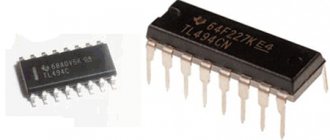
controller. For example, one of the most common is TL494. The circuit of the master oscillator based on it is shown above. In general, a typical connection diagram for any other microcircuit can be found in the technical documentation for it (datasheet).
Calculation of power supply pulse frequency
The K1156EU2 controller is intended for use as a control circuit for pulsed secondary power supplies operating at frequencies up to 1 MHz. Thanks to its high performance, the microcircuit has found wide application and proven itself well. If there is no domestic version of the controller, it can be replaced with analogues such as UC1825, UC2825, UC3825. The controller's half-bridge output stages are designed to drive large capacitive loads, such as the gates of power MOSFETs, and switch both sink and sink current. The description of the K1156EU2 pins is as follows:
It is also worth noting that the frequency of the pulses depends on the values of the resistor and capacitor at pins 5 and 6 of the microcircuit. Moreover, the capacitance of the capacitor is responsible for the pause (the so-called dead time) between pulses. And this directly affects the simultaneous closing of the output switches in order to avoid through currents. The question is especially relevant at high powers. The resistor resistance is selected from the range of 3...100 kOhm, the capacitance of the capacitor is 0.47...100 nF. Nomograms for selecting these radio components are shown below in the figure:
Thus, to provide a dead time of ? 1.5 μs (to reduce the likelihood of through currents through the MOSFET in the power stage), a capacitor with a capacity of 15 nF (0.015 μF or 15000 pF) will be needed. Now look at the left graph. Frequency will be discussed further below. At this stage, we will take 60 kHz as the nominal one. This means that a resistor for our master oscillator is needed with a nominal value of ? 3 kOhm. Let's set the trimmer to 4.7 kOhm. They can slightly increase the frequency, thereby increasing the power of the power supply as a whole.
Synchronizing two or more PWM controllers
An important function of K1156EU2 is their joint use. Those. one generator will be the master and the other will be the slave. For this purpose, there is a functional 4 synchronization pin. As a result, you can get two synchronously operating PWM generators. There are many applications for this method. Since the generators will operate synchronously, each of them can be loaded with a separate output stage with power switches and a pulse transformer. In this case, transformers of smaller overall power can be used. So, if we need a total power of a switching power supply of at least 600 W for 4 UMZCH, then we can use two 300 W transformers with two UMZCH connected to them. Accordingly, we will be able to remove part of the load from the transistors of the power stage, the winding wire, and we will also need a smaller core. In this regard, you can even save on the purchase of radio components for the future UPS. The synchronization circuit for two PWM controllers (master and slave) looks like this:
However, for general educational purposes, we will limit ourselves to the inclusion of K1156EU2 in a single (standard) version, because Our goal is to give you general development skills. And the rationality of using this or that circuit or technical solution will depend on the purpose of using a switching power supply.
We've sorted out the first functional module of the future secondary power supply unit. We finally accept the circuit design version of the generator based on K1156EU2, as shown in the figure above under number 1. If necessary, at the final stage of design, the ratings of the parts can be adjusted, which, in fact, will not affect the functional diagram of the generator.
Selection of power switches for the power supply
Now let’s talk about what the K1156EU2 or TL494 PWM controller or any other IC will control. MOSFET transistors as power switches
as the most effective. As for bipolar ones, their significant disadvantages are increased residual voltage on the collector in saturation mode, high control power in the base circuit and long resorption time. All this leads to a significant decrease in the efficiency of the keys. But IGBTs or insulated gate bipolar transistors are too expensive and not very common. So the choice falls on MOSFET.
Let's determine the boundaries of the selection of MOS transistors. According to the conditions, we need a switching power supply with a power of 600 watts from a 220 volt power supply. This means that after rectifying diodes and a filter capacitor, 220 volts of alternating current are converted into 300...310 volts of direct current. This is at a nominal voltage of 220 V. But the electrical network can be either 175 or 250 volts. The current strength in the circuit will be nominally equal to I=P/U or I=600 W/300(310) V=1.94…2 amperes.
The future pulse converter will be of a push-pull type
, because
single-cycle ones have proven themselves well at powers up to 100 watts. We select the circuit for connecting the power stage of a push-pull switching power supply from three existing ones. This, as was said, is full-bridge, half-bridge or with a midpoint (push-pull). The latter circuit is most efficient with input voltages up to 100 volts and power up to 500 watts. In principle, you can use a push-pull switching circuit, but we will not repeat it, because it is precisely the topic of discussion in the article “1000 VA Converter Circuit”. Half-bridge and bridge circuits are effectively used at higher input voltages (and we have 310 V) and with powers up to 1 kW in the first case and above 1 kW in the second case. A half-bridge circuit
is suitable for us .
Let's take the switching frequency of power transistors to be about 60 kHz. Due to possible frequency drift, it may increase to 65 kHz. You can, of course, increase the frequency to 100 kHz, or even more. However, many magnetic materials used as pulse transformer cores are not capable of operating at such frequencies. In addition, as the frequency increases, we will need high-frequency rectifier power diodes. But they are not cheap and difficult to access for many. In addition, after a full-wave rectifier, the frequency doubles. So we will limit ourselves to a frequency of 60 kHz, as the most optimal.
Now we will determine the amplitude of the rated voltage on the primary winding of the pulse transformer, taking into account the voltage drop across the transistor junction. U=310/2 – u, where u is the voltage drop across the MOSFET junction. Since we have not yet chosen the transistors, we will take on average u = 0.7 V. Hence U = (310/2) -0.7 = 154.3 V. The minimum amplitude when the network voltage drops to 175 volts will be no more than 123 V, and the maximum when increasing to 250 V is no less than 176 V. To select MIS transistors, we proceed from the maximum permissible current (600/123 = 4.8 A) and voltage (176 V). According to calculations, we need a MOSFET with a drain-source voltage of 200 volts and a maximum permissible current through the junction of at least 6 amperes. These conditions are met, for example, by IRF630, 2SK1117, 2SK1917, IRF740, IRFP460, IRF830, etc. Here, again, we proceed from availability and cost. For our example, let's take IRFP460. The power keys were picked up.
We select the rectifier bridge diodes at the input of the switching power supply taking into account a reverse voltage of 400 volts and a current of 2 amperes (600/(175 V * 2 pcs.) = 1.71 A) with a bridge circuit. We take a diode bridge type KBU810. The network rectifier circuit will look like this:
Resistors R1 and R2 are ballast and are used to discharge high voltage capacitors for safety purposes.
Calculation and winding of a pulse transformer
Now let's calculate the pulse transformer.
Transformer calculation is the most complex, important and “subtle” part of the entire calculation of a switching power supply. To do this, it is most effective to use computer programs, the most popular of which can be found on our amateur radio website. Links to programs for calculating a transformer and their detailed descriptions are also found in the above-mentioned articles.
So, we have as initial data a supply voltage range of 247...355 V (with a network voltage deviation of 175...250 V), a power of at least 600 watts, an effective magnetic circuit induction from 0.1 to 0.2 Tesla, an effective magnetic permeability of the magnetic circuit at When used as a core, a ferrite ring of grade M2500NMS1 K65x40x9 is 1800...2000. Above is the actual mains voltage for calculating a pulse transformer in the Design tools pulse transformers 4.0.0.0 program and similar ones (see articles). However, as I advised, it is better to apply the programs all at once in a comprehensive manner. Accordingly, in some it is necessary to indicate the voltage directly on the primary winding of the pulse transformer. A little higher we provided a diagram of a network rectifier for powering a pulse unit. As you can see, there the mains voltage is converted into bipolar +/-154.3 V using a divider. The nominal voltage is indicated for a mains voltage of 220 V. Accordingly, with a mains voltage deviation of 175...250 V on the primary winding, it will fluctuate between 247... 355 volts (this is after rectifier diodes and filter capacitors), and 247/2-0.7...355/2-0.7, i.e. 122.8…176.8 volts. Be careful!
We think that with the help of programs it will not be difficult to determine the main characteristics of the required pulse transformer. For the K65x40x9 ring we took, we have the following. Efficiency is about 98%; the number of turns in the primary winding is about 55 with a diameter of 1.2 mm; the number of turns of each secondary winding for voltage +/-30 V is 10+10 with a tap from the middle of the wire with a diameter of 1.5 mm. We know all the data for winding the transformer. As a result of self-production, you should get something similar, and maybe even better (it is better to place the windings more evenly around the ring):
Let's move on directly to the circuitry part of the development.
Designing a UPS electrical circuit diagram
We have already determined that our switching power supply will be push-pull with a half-bridge connection of the power final stage, consisting of two powerful MOSFET IRFP460. The K1156EU2R microcircuit was chosen as a PWM controller. Now we are faced with the task of combining all three functional modules, each of which has its own electrical circuit. Instead of reinventing the wheel, we can modify the existing standard electrical circuit of an already designed UPS on the controller we have chosen. Ultimately, we got this version of the switching power supply circuit:
As you can see, it includes all three modules we discussed above.
Additionally, using a relay and a limiting resistor R1 (type C5-16MB or C5-5B), a soft start is implemented at the input, allowing to avoid sudden surges of current. The relay can be used for voltages of both 12 and 24 volts with the selection of resistor R19. Varistor RU1 protects the input circuit from pulses of excessive amplitude. Capacitors C1-C4 and two-winding inductor L1 form a network noise suppression filter that prevents the penetration of high-frequency ripples created by the converter into the supply network. L1 is wound until the window is filled with a wire of diameter 0.5 mm on a magnetic core Ш7x7 made of alsifer ТЧ60, ТЧК55 or ferrite type 2000НМ. The inductor windings contain an equal number of turns. You can use a magnetic core of type K24x14x7. Then wind 50 turns into 2 wires.
Trimmer resistor R16 and capacitor C12 determine the conversion frequency. To reduce the self-induction emf of transformer T2, damper diodes VD7 and VD8 are connected in parallel to the transistor channels. Schottky diodes VD2 and VD3 protect the switching transistors and outputs of the DA2 microcircuit from reverse voltage pulses.
Current transformer T1 is wound on a ferrite ring K10×6×3 grade 4000NM or on K12×8×3 grade 2000NM. The primary winding contains 1 turn of wire with a diameter of 0.5 mm or mounting wire in polyvinyl chloride insulation. The secondary winding is 100 turns with a tap from the middle of the PELSHO wire with a diameter of 0.06...0.12 mm. The windings should be insulated, for example, with varnished cloth. Current flows through the primary winding of transformer T1. The voltage of the secondary winding through resistor R12 is supplied to the input of the current comparator 9 pin of the DA2 microcircuit. At the moment when the voltage at this input exceeds the comparator threshold (1 volt), the generation of excitation pulses will stop. The protection response current depends on the number of turns of the secondary winding of transformer T1, the capacitance of capacitor C8 and the resistance of resistors R8, R9 (tuning), R12.
From the moment it is connected to the network until the inverter is excited, the K1156EU2R microcircuit receives power from a parametric voltage stabilizer on resistor R2 (the resistance of which may need to be reduced) and zener diode VD4 through diode VD5. In this mode, the microcircuit consumes a current of no more than 2 mA. After excitation of the inverter, the PWM controller powers the auxiliary rectifier VD13-VD16, the voltage from which is stabilized by the KR142EN8V microcircuit (or any other with a stabilization voltage of 15 volts). Diodes VD5 and VD18 eliminate the mutual influence of the two power supplies of the K1156EU2R microcircuit.
Optocoupler U1 provides galvanic isolation of the feedback circuit. The OS circuit is needed to stabilize the output voltage of a switching power supply. If it exceeds the nominal value, the current through the zener diode VD17 and the emitting diode of the optocoupler will increase sharply. As a result, the phototransistor of the optocoupler opens. The voltage at the input of the voltage feedback comparator increases (1 leg of the microcircuit). The duration of the pulses at the generator output is reduced. This causes the output voltage to drop to the nominal level.
The operating principle of the switching power supply circuit should be clear. Now let's move on to tips on designing a printed circuit board layout and installing radio components.
Tips for installing and manufacturing a printed circuit board for a UPS
To ensure the operation of a powerful switching power supply, it is necessary to pay special attention to the arrangement of elements on the printed circuit board and their wiring connections. Long conductors can cause parasitic inductance and unnecessary emf, which will ultimately lead to lasing. This results in a sharp increase in power consumption and a malfunction of the generator, which will certainly affect the operation of the output power switches in the form of their breakdown by through currents. Therefore, the lengths of all conductors should be minimal, the leads of the capacitors should be short (especially blocking ones, smoothing out RF pulsations). On the mounting side on the printed circuit board, under the radio components of the master oscillator and the PWM controller, there should be plenty of space left for the screen. Capacitor C21 should have low self-inductance. It must be located no further than 6 mm from pin 15 of the DA2 chip to suppress high-frequency interference. High-current circuits must be kept to a minimum length. The width of the tracks of high-current circuits is selected as 5 mm or more. For low-current circuits, a track width of 0.8...1.5 mm is sufficient. In this case, one should proceed from the dependence of 0.5 ampere current per track width of 0.5 mm. Taking into account copper etching, the minimum width is 0.8 mm. In a place where it is impossible to lay a large-width track, when tinning, a layer of solder is soldered onto it or tinned wire is soldered along the entire length, thereby increasing the thickness.
In conclusion, it’s worth spending a few words on such a bad phenomenon as the skin effect
.
As a result, high-frequency alternating current, when flowing through a conductor, is not distributed evenly over the cross-section, but mainly in the surface layer. This can have dire consequences for our pulse transformer at high powers. Therefore, it is recommended to wind the power windings of the transformer not with a single wire of large cross-section, because there will be no benefit from it, but a “pigtail” woven from several wires of smaller diameter. The result is a kind of Litz wire
. Thus, we will improve the quality factor of the windings, increase the efficiency and quality of the pulse transformer. Notice how the primary winding is wound:
There are 8 pigtails in the photo with 15 wires each. Looks solid, doesn't it?
Epilogue
This, as it turns out, is far from short article discusses the most important aspects of designing pulsed power supplies, which every radio amateur who decides to create an SMPS will definitely encounter. We tried to describe the entire algorithm of actions as clearly as possible. We examined in more detail the points that are worth emphasizing. Post any additional tips and tricks in the comments.
Radio amateurs are interested in electrical circuits:
Laboratory power supply
Network power supply for CB

