The kits were well packaged and there was no damage to the contents. Assembly instructions were sent via email. For tools you will need a soldering iron, screwdriver, pliers and insulated wire. The body is powder coated steel. It also includes a removable ventilated cover.
Parameters and description of the kit
- Rated power: 25W RMS
- Input sensitivity: 1.5V
- Input impedance 100 kohms
- Input Connector: Linear RCA
- Speaker output: 4 and 8 ohms
- Distortion: Less than 0.5% half power, 1% full power.
- Frequency range: 8 Hz - 20 kHz +0/-1dB at rated power
- Signal to noise ratio: less than 80dB
- Lamps: Gold Lion KT88, NOS JAN Philips 5751
- Power consumption: 80 W (each monoblock)
- Weight: 6 kg (each monoblock)
- Dimensions: 200 mm (W) X 220 mm (H) X 300 mm (D)
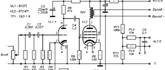
Tube amplifier on KT88 - circuit diagram
The first stage, after the audio signal input, is an SRPP amplifier based on a 5751 tube, this is a miniature double triode. But other tubes can also be used in the driver; the closest analogue is 12AX7, which will provide additional amplification. Another 12AU7, ECC82 and ECC802S can be used, but they will not be able to provide enough gain to drive the KT88 to its full power.
The output stage is an inverting Push-Pull amplifier, which is based on standard switching. There is only one coupling capacitor throughout the entire signal path, which is very good. The elegance and absolute simplicity of this amplifier circuit will appeal to all audiophiles who prefer as few components as possible in the signal path.
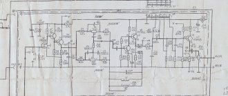
Power supply for lamp UMZCH - electrical diagram
A constant current source consisting of a voltage regulator on the LM317HVT is used to stabilize the output stage current. The bias current can be adjusted by changing the current resistor setting (10-22 ohms), and this will allow you to use many different radio tubes during experiments. A switch is included for convenience and can be used to easily adjust the bias current. Lamps of type 6550, KT88, KT90 can be installed here.
Quite good quality components are used in the amplifier set. Russian-made paper-in-oil (PIO) transfer capacitor. The type is labeled K40U-9 (0.33uF/630V), which sounds good and is popular among audio enthusiasts. But feel free to experiment with various other capacitors. Resistors are carbon films. Output transformer - Edcor CXPP25-MS-8k, 25 W.
Power is supplied to the ULF through a connector located on the rear panel of the amplifier. At the 220 V input there is a 3 ampere fuse and a noise filter. Edcor power transformer with output windings 180V-0-180V at 250 mA and 12V at 4A. 12V DC power is used for filament lamps. A circuit based on LM555 and a relay is used to delay the supply of power to the anodes.
Power supply for a homemade tube amplifier.
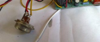
I’ll start the assembly with the power supply and describe it at the same time. The heart of the power supply (and of the entire amplifier, probably) will be the TST-143 toroidal transformer, which I once (4 years ago) tore out of some tube generator right as it was being taken to a landfill. Unfortunately, I didn’t manage to do anything else. It’s a pity for such a generator, but maybe it was still working or could have been repaired... Okay, I digress. Here he is my security officer.
Of course, I found a diagram for it on the Internet.
The rectifier will be on a diode bridge with a filter on the inductor for anode power. And 12 volts to power the backlight and anode voltage delay circuit. This is the throttle I have.
Its inductance was 5 henry (according to the device), which is quite enough for good filtration. And the diode bridge was found like this.
Its name is BR1010. (10 amps 1000 volts). I'm starting to cut out the amplifier. I think it will be something like this.
I mark and cut holes in the PCB for the sockets for the light bulbs.
It's turning out pretty good as long as I like it.
Then I start to figure out how to arrange all the details on this PCB.
This way and that way. drilling sawing
test
Something began to emerge.
I found a fluoroplastic wire in old supplies and immediately all the alternatives and compromises regarding the wire for installation disappeared without a trace .
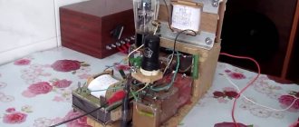
This is how the installation turned out. Everything seems to be “kosher”, the incandescence is intertwined, the ground is practically at one point. Should work.
It's time to fence in food. After checking and testing all the output windings of the trans, I soldered all the necessary wires to it and began installing it according to the accepted plan.
As you know, in our difficult amateur radio business, you can’t go anywhere without improvised materials: this is how the Kinder Surprise container came in handy.
And a Nescafe lid and an old CD
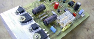
Next, I install the rectifier and power filter elements.
I tore out the capacitors from the boards of TVs and monitors. All containers are at least 400 volts (I know that I should have more, but I don’t want to buy them).
I bridge the bridge with containers (whatever were on hand, I’ll probably change them later)
It turns out to be a bit much, but oh well, it will sag under load
I use the standard power switch from the amplifier (clear and soft).
We're done with that. Well done
Backlight for tube amplifier housing.
To implement the backlight, an LED strip was purchased.
And installed in the housing as follows.
Now the glow of the amplifier will be visible during the daytime. To power the backlight, I will make a separate rectifier with a stabilizer on some KRKEN-like microcircuit (which I can find in the trash), from which I plan to power the anode voltage supply delay circuit.
Delay relay.
Having rummaged through the bins of my homeland, I found this completely untouched thing.
This is a radio time relay designer for a photo enlarger.
We collect, check, try on.
I set the response time to about 40 seconds, and replaced the variable resistor with a constant one. The matter is coming to an end. All that remains is to put everything together, install the face, indicators and regulators.
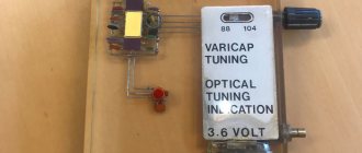
Regulators (input variables)
They say that sound quality can greatly depend on them. In short, I installed these
Dual 100 kOhm. since I have two of them, I decided to parallel the pins, thereby obtaining 50 kOhm and increased resistance to wheezing
Indicators.
I used standard indicators, with standard backlighting
I mercilessly copied the connection diagram from the original board and used it as well.
This is what I ended up with.
When checking the power, the amplifier demonstrated an output voltage of 10 volts of an undistorted sine wave with a frequency of 1000 Hz into a 4 ohm load (25 watts) equally across channels, which was pleasing
When listening, the sound was crystal clear without background and dust, as they say, but too monitory, or what? beautiful, but flat.
I naively believed that he would play without timbres, but...
Using a software equalizer, we managed to get a very beautiful sound that everyone liked. Thank you all very much!!!
ULF on KT88 - assembly and setup
To assemble the kit, you only need to have basic soldering skills, and the whole job will take several evenings. The kit contains many parts, but following the instructions will ensure successful results. Before you start installing the equipment, you need to study the circuit diagram so that it is imprinted in your memory - it will be easier to assemble it, knowing approximately what goes where.
Power supply and adjustment of the balance between the output stage lamps. This is done using a multimeter, which is inserted at the test points on the top of the amplifier and then adjusted with a 25 ohm potentiometer. After an hour of work, you should check the balance again. I had a discrepancy of only a few milliamps over a month of daily use.
After balancing the offset, I connected the Fostex FE206E acoustics (96 dB / 1 W) and checked for hum. Everything is fine. For the PSU, I was hoping to get about a 60 second power-up delay, but couldn't get more than about 30 seconds.
The radiator for the LM317 was quite hot - about 100 C (the maximum operating temperature of the LM317HVT is 125 C). The temperatures of the power transformer and audio output were 65 C to 45 C respectively.
Tube ULF
Diagram of the Astra-2 tape recorder for 6N2P, 6N1P, 6P14P and 6E1P (2W)
The “Astra-2” tape recorder was produced by one of the factories in Leningrad. The tape recorder allows you to record from a microphone, pickup, radio, broadcast network and re-record phonograms from other tape recorders. Rated output power...
1 4676 0
Scheme of three-way tube UMZCH G. Mudretsov on 6N1P, 6P14P
G. Mudretsov (MRB-1974) preceded his scheme for a three-band high-quality UMZCH with lengthy discussions about the need to divide frequencies into channels. In some amplifiers, this separation is carried out at the output: the amplifier amplifies the entire frequency band, and the signal is divided into two bands...
4 8018 0
Scheme of two-channel tube UMZCH B. Jaunzems on 6N2P, 6P14P (2W+4W)
Below is a circuit that is very similar to Romanyuk’s circuit - it is a two-channel low-frequency amplifier by B. Jaunzems (MRB-1974). Below is a diagram of a simple two-channel amplifier assembled using five finger tubes. The amplifier reproduces a frequency band from 50 Hz to...
1 5662 0
Scheme of a two-channel UMZCH using 6N2P, 6P14P (30W) lamps
A fairly powerful, high-quality two-channel UMZCH from the book MRB-407/1961 is assembled using 11 lamps. The amplifier output power is 30 W with a nonlinear distortion coefficient at a frequency of 400 Hz of less than 0.5%. The reproduced frequency band is 30...15000 Hz...
1 7058 1
ULF circuit on lamps 5Zh2p, 6N3P, 6P14P Yu. Romanyuk (6W + 2x2W)
Using two channels of amplification of higher frequencies and one channel of amplification of lower frequencies, high-quality signal reproduction can be obtained in the stereo amplifier of Yu. Romanyuk (R-10/65). The electrical and acoustic parameters of the amplifier meet the requirements for stereo amplifiers...
2 4846 0
Two-channel ultra-linear ULF on lamps 6N2P, 6P14P by A. Mezherovsky (8W)
The two-channel ultralinear UMZCH A. Mezherovsky (R-5/68) uses a very rare method of channel separation using deep negative feedback, the voltage of which is supplied from both output transformers to the cathode circuit of the separating stage lamp...
0 5834 0
Scheme of a two-channel UMZCH using lamps 6Zh32P, 6N2P, 6P14P G. Karasev (24W)
A high-quality stereophonic installation, designed by engineer G. Karasev (R-3/66), consists of a four-channel amplifier and two broadband acoustic units, each of which contains five dynamic loudspeakers. Strengthening the input sound...
1 6913 0
Transformerless ULF on EL84, UL41 lamps F. Kuehne
For more powerful amplifiers, the following circuit of an already well-known author is suitable - a two-channel transformerless final stage of F. Kuehne. The operating principle of this circuit, assembled on EL84 and UL41 pentodes, is based on the fact that one of the lamps (L2) operates in ...
1 7016 0
Two-channel ULF A. Slonim on lamps 6ZH1P, 6N9S, 6N5S (4W)
A. Slonim’s two-channel amplifier (R-9/67), which is simple in its set of parts, can easily be confused with a simple circuit, but the main features of a complex circuit indicate that the amplifier in question is correctly classified in this classification article. Its diagram is given below, it is intended...
1 5841 0
Diagram of a bridge stereo UMZCH by K. Weisbein using 6N1P, 6P41S (20W) lamps
Below is a diagram that was published in the magazine “Radioamator” - a diagram of a stereo bridge UMZCH by K. Weisbein (RA-3/99). The author believes that the output transformer is the most critical component of any high-quality audio amplifier,...
2 8986 5
3