The goal of this project was to assemble a simple tube amplifier with your own hands. The main difficulties that radio amateurs who decide to assemble a tube amplifier have to face are the manufacture of transformers and housing. They were overcome by using unified TAN transformers and ready-made housings from Gainta. And although this amplifier cannot be classified as hi-end, it will be of interest to radio amateurs who decide to get involved in tube sound.
↑ Power supply with under-under-you-under-vert. Lazy IIP
Before this, I had already read an article on Datagor by the respected AlexD about a 6P6S amplifier and a switching power supply: I called it “Cube”.
Compact tube amplifier with UPS. Therefore, I settled on the diagram from Alexey’s article. And if you do it, then only with an impulse generator. There are many reasons - it is becoming difficult to find iron and wire even for weekenders, and my conscience did not allow me to spend an entire trance as a power supply. Nowadays, a pretty good UPS can be purchased for relatively little money and everywhere. Light weight. Although the plus here is doubtful, I have met people who measure the “coolness” of an amplifier precisely by weight. They say I installed it - the shelf broke, this is a real high-end. Well, I just wanted to assemble an impulse generator.
But somehow it didn’t work out with repeating the UPS. I spent a lot of time, money and PCB, but instead of a power supply I got pretty good detonators. Hence the conclusion that apparently the curvature of the arms does not allow... Then I decided to take a regular ATX power supply from a PC and raise the voltage on the +5V bus to 6.3V and use it as a filament.
The easiest way to do this is with an ATX block using tl494 PWM. All elements that hang on legs 1, 2, 3, 4, 13 and 14 must be removed and instead assembled exactly as in the diagram above.
Fragment excluded. The full version is available to patrons and full members of the community.
1 leg - PWM error amplifier, it is on this leg that the adjustment will be made 2, 3 - frequency-dependent feedback 4 - “soft start” of the power supply. It is regulated by the capacitance of capacitor C2. Resistor R1 can accurately set the filament voltage.
Almost all computer UPSs can be converted using this principle. I was able to raise the +5V rail to 6.3V on many PWMs. And only with sg6105 it didn’t work out - maximum 6V, no matter what. It is the most harmful in my opinion, it is difficult to “deceive”. FSP UPSs are very good. They assemble it quite well and always install their own design - the SFP3528 module.
For clarity, a diagram of the power supply and what needs to be unsoldered
Fragment excluded. The full version is available to patrons and full members of the community.
Converted power supply
Half the battle is done, now the anode!
And then a problem arose.
I tried rewinding the power trans. But the power supply began to work unstably, the keys got very hot. And the creations of Chinese masters that were more prone to suicide generally burned down. In general, after experimenting, I decided to try attaching an additional transformer for the anode voltage. And it worked! Additional trans data:
I - 16 turns PEV2 - 2 mm II - 150 turns PEV2 - 0.36 mm
Fragment excluded. The full version is available to patrons and full members of the community.
The ferrite was also removed from the UPS. You can buy it, but the main thing is that there is no gap in the central core. To disassemble the transformer, you need to boil it in water for 10-15 minutes. After the glue softens, you can pull out the 2 halves of the ferrite. Here it is better not to pull with a fool, but to gently rock the halves, since ferrite is very fragile. If it does break (which probably will), it can be glued together with super glue.
Next, I unwind all the windings from the holder.
And I start winding my transformer. I'm winding the primary. The primary is wound all at once, in one layer. Here you need to remember the winding direction. All windings must be wound in one direction. It is important.
The secondary is wound at the rate of approximately 1 turn - 2 volts. You may ask - why such a thick wire? The entire winding fits easily on the frame; there is no need to push it in. The anode + bias winding winds without problems. That’s why it’s better to have a reserve. And it is more convenient to wind a thick wire than a thin one.
Wound secondary
and assembled transformer
Now we need to connect our additional trans to the power supply. To do this, I connect the primary of the additional trance to the secondary of the power one (the winding from which is formed into the +12 Volt bus). That is, you need to solder to the terminals of the secondary winding of the standard UPS trans. The winding pattern may differ for different power supplies. To check, you need to measure the alternating voltage at the secondary terminals with a tester - there should be approximately 20 Volts alternating.
Such a connection does not disrupt the operating mode of the computer UPS and is essentially a normal load.
Amplifier with combined feedback
Despite their high performance, both conventional pentode and ultralinear amplifiers were rarely used without general feedback. The use of OOS reduces the output impedance of the amplifier and improves the operating conditions of low-frequency heads.
But to reduce the output impedance of the amplifier, you can use not only negative, but also positive feedback. The next amplifier circuit uses combined feedback.
Rice. 5. Schematic diagram of an ultralinear tube amplifier based on 6N2P, 6N1P and 6P14P.
The main feature of the amplifier is the combination of OOO for voltage and POS for current, which improves the matching of the amplifier with the dynamic head in the region of the main mechanical resonance.
The PIC signal is taken from the current sensor (R19) connected to the ground terminal of the output transformer. The depth of both feedbacks is adjusted synchronously, which eliminates self-excitation of the amplifier.
The first stage is a voltage amplifier. The bass reflex is made according to a cathode-coupled circuit. The output stage is made according to a standard ultralinear circuit and is complemented by a balancing regulator RP1. The second triode VL1 is used as a microphone amplifier.
The output transformer is made on a Ш25x40 core. The primary winding contains 2x(1100+400) turns of wire d=0.18mm, the secondary winding contains 82 turns of wire d=0.86mm (6Ohm)
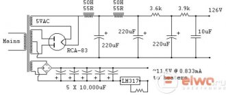
↑ Smooth supply of anode
A smooth supply of anode voltage is also needed.
Otherwise, when starting to charge the containers, the power supply will operate at low resistance and will go into protection. Fragment excluded. The full version is available to patrons and full members of the community.
Only ultrafasts are suitable for the diode bridge. Slower ones will get very hot. Capacitors C1 and C2 regulate the delay time. With 10 µF the output to operating mode is about 3 minutes. Any field switch with a suitable voltage will do. It will need to be hung on a small radiator, because at the moment of opening the field will heat up. Well, it is advisable to hang something in the anode load, otherwise the output voltage will differ more. I hang two 220V x 40W lamps connected in series as a load.
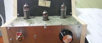
Photo of the finished device. This board is for a different amplifier, differs only in the presence of a bias winding.
Push-pull triode-pentode amplifier
The desire to reduce, if not the number of tubes, then at least the number of cylinders, led to the appearance of an amplifier circuit based on two triode-pentodes. Low-frequency triode pentodes were once specially designed for single-ended amplifiers of receivers and televisions (the triode part was used in the driver, the pentode part in the output stage).
Rice. 3. Schematic diagram of a push-pull tube UMZCH based on triode pentodes (6BM8, 6F3P, 10 Watt).
Bass reflex circuit with a shared load, direct connection with the first stage. The output stage is pentode with fixed bias. Variants of this circuit with ultralinear switching of output lamps, with combined and automatic bias are also known. The design details of the transformer are unknown.
The R3C2 circuit provides stability to the OOO closed loop amplifier.
↑ Amplifier circuit
The scheme is practically unchanged - according to Alexey’s article, I called it “Cube”. Compact tube amplifier with UPS
Only C1 was added to the 6n9s cathodes.
Assembled board
↑ Weekend trances - 80% of the success of any lamp player
I wound the output trances on PL hardware from the TS-90. You need to choose iron based on the following calculation: Sound power = 1/5 of the Overall power. Their maximum output power is about 15 watts. Suits us! Winding data
I - 4000 volts with 0.23 mm wire II - 80 vit with 0.9 mm wire for a load of 4 Ohms + 30 vits for 8 Ohms.
A very convenient thing is taps for different loads if you have several pairs of acoustics. The lower limit of playback was calculated at 15 Hz. Primary and secondary in series.
Here is the winding diagram for 1 coil. And a diagram for connecting the windings of 2 coils.
Fragment excluded. The full version is available to patrons and full members of the community.
When assembling the output transformer, it is necessary, and it is MANDATORY, to apply a thin layer of magnetic varnish to the ends of the core halves that are adjacent to each other, and only after that can the magnetic core be pulled off. Magnetic varnish is prepared on the basis of carbonyl iron powder, which is used in various electromechanical devices, and nitro varnish of the NTs brand. During preparation, the powder is added to the varnish in small portions with continuous stirring until a homogeneous mass with the consistency of liquid sour cream is obtained. The resulting mixture must be used immediately within 2-3 minutes. I do not recommend using glue such as BF, KS, “Mars” or the like, much less epoxy, to prepare magnetic varnish, since it may require disassembling the transformer, which in this case will be very difficult to do. In the absence of factory-made carbonyl iron powder, it is not difficult to prepare it yourself. To do this, it is necessary to grind the carbonyl iron core using a needle file or simply crush it using pliers. You cannot use sandpaper or an abrasive stone for this operation, since quite large and very hard foreign particles can get into the powder. It goes without saying that the core must be ground as finely as possible and, since It has little strength, this will not be difficult to do.
Setting up the amplifier has no special features. First, as usual, the operating modes of the lamps are set to DC, then the phase-inverse stage is balanced at frequencies of 100 Hz and 18-25 kHz. The only difference specific to the circlotron is that to test the final stage, the vertical deflection amplifier of the oscilloscope must have a differential input that is connected to the output winding (for example, pins 1 and 1′) of the autotransformer.
In addition to cross-feedback operating in the high-frequency region, the amplifier has three more feedback loops that operate over the entire audio frequency range. The first of them covers the final and pre-output stages. Its signal is removed from the anode loads of the output lamps VL5-VL8 and is supplied through chains C12R18, C13R22 to the cathodes VL3 and VL4, respectively. The second OOS circuit operates only in the final stage. It occurs due to the use of ultra-linear switching of output lamps. And finally, the third chain is the general OOS loop. Its voltage is removed from the secondary winding of the output transformer and, through a ns-chain consisting of resistor R13 and capacitor C8, is supplied to the control grid of the VL1.2 lamp. Correction capacitor C8. It eliminates self-excitation of the device at ultrasonic frequencies. Its capacity depends on the installation’s own capacity, the depth of feedback and a number of other factors and is selected experimentally. Resistors R2 and R13 form a voltage divider. Its parameters determine the depth of the overall environmental protection. With the element ratings indicated on the circuit diagram, the amplifier has a sensitivity of about 1.5 V. In the case where higher sensitivity is required, it is necessary to reduce the feedback depth by increasing the resistance of resistor R13.
At this point, I think it would be useful to make a small digression and say a few words about OOS. The fact is that recently there have been fierce debates between supporters and opponents of the use of feedback in the sound reinforcement path, with both sides giving quite reasonable arguments and counterarguments. Without going into the details of this discussion, I recommend that readers try the idea proposed by one of the gurus in the field of vacuum tubes, David Manley, and answer the question themselves. The idea comes down to this. A number of devices manufactured by Manley Audio Laboratories, for example, the Manley The Purist preamplifier ($1600), or the Manley SE/PP 300V power amplifiers ($5500), provide smooth adjustment of the feedback depth from 0 up to 10...12 dB. With its help, you can change the sound character of the equipment in accordance with the individual tastes of the listener, the characteristics of the room, etc. I would like to warn those readers who are interested in this proposal about several pitfalls. We are not talking about changes in the nominal sensitivity and operating bandwidth of the device, damping coefficients and nonlinear distortions. These problems are obvious, and the issues surrounding them are sufficiently well researched that they can be taken into account with relative ease. It is much more difficult to take into account the influence of parasitic capacitances and inductances of the installation, since they, together with the resistances of the resistors included in the OOS circuit, form various filters, and when adjusting the feedback depth, the frequency response and phase response of the OOS loop will change. The consequences of this can be the most unpredictable. To reduce these problems to a minimum, it is necessary to carefully consider the installation topology, “all the way” to reduce parasitic connections and reactivity. In addition, we must not forget that variable resistors have their own capacitance, as a result of which their bandwidth depends on the angle of rotation of the engine. Therefore, conducting such an experiment requires serious preparation and careful selection of high-quality components.
The final stage is made according to a push-pull ultralinear circuit using VL5-VL8 lamps. The circuits of their control grids contain anti-parasitic elements - R23, R24, R27, R28 and leakage resistors R19, R21, R25, R26. The variable resistor R20, included in these circuits, serves to balance the arms of the output stage with respect to direct current. Its middle pin is connected to the negative of the bias voltage source. The output voltage of this source when setting up the amplifier is selected within -25. ..-30 V so that the anode quiescent current of each lamp is 60 mA. In order to increase the output power to 35 W, parallel connection of lamps was used. In this case, the optimal load resistance in the anode circuit is 2.7 kOhm. Since the final stage contains 4 lamps, it was necessary to take measures designed to compensate for the production and technological variation in their characteristics. To solve this problem, two-watt cathode resistors R29, R30, R33, R34 are used. Current-limiting resistors R31, R32, R35, R36, connected in series with screen grids VL5-VL8, are not only compensating elements, but also reduce the risk of electrical overload of these electrodes. The inclusion factor of the screen grids is 0.42.
The output transformer is made on the basis of a ShLM-40x50 magnetic core with a window size of 24x72 mm. Cores of this size are used in OSM-0.4 transformers. The primary winding contains 3120 turns of 0.355 mm PEV wire. It is divided into two halves of 1560 turns, each of which is placed on its own side of the coil frame. To do this, the frame is divided into two equal parts by a vertical partition. It is necessary to make a slot in the partition through which the conductors of the secondary windings are passed during the process of winding the coil. Each of the halves of the primary winding is divided into 4 unequal sections. The uneven distribution of wire across sections is caused, on the one hand, by the desire to simplify the removal of 42% of turns, and on the other, by the need to have an even number of layers in each section. Failure to comply with the last condition significantly complicates the manufacture of the transformer coil, and also deteriorates the quality of the winding. The primary winding sections have the following design. Sections 1 and 8 each contain 520 turns, laid in 8 layers; 2, 4, 5 and 7 each have 390 turns, which are wound in 6 layers, and finally, sections 3 and 6 have 260 turns each in 4 layers. Each layer of any section of the “primary” consists of 65 turns. The secondary winding consists of two parts connected in series, which allows the proposed amplifier to be used with acoustic systems with a resistance of 4 and 8 Ohms.
However, we will return to the specifics of choosing capacitors installed in the cathode circuit of the lamp when studying the final stage. For alternating current, the second and final stages are connected to each other by separating C4. This element affects the sound quality in the most radical way and therefore a conversation about the requirements for its quality deserves special attention. Let us immediately note that an ideal component that would not spoil the sound at all simply does not exist in nature. These could include vacuum or air capacitors, but it is very problematic to imagine, much less implement in practice, an amplifier with a “feedthrough” the size of a pair of tank batteries. Therefore, the choice of type C4 is always a compromise. Of course, you can simply note the high quality of specialized audiophile products from companies such as Jensen Capacitors or the exotic “spill” Audio Note, and call it a day, but the exorbitant price of such components instantly transforms them into the category of equally outrageous dreams for almost all radio amateurs. Let us dwell in more detail on the actually available elements of general use of domestic production. According to many developers of audio equipment, paper-oil and paper-foil products of types K40-9-5 (with 5th acceptance) are considered the best; K40-U9; K40A-2; CBG; OKBG; BM-2; BMT-2. A little worse are metal and paper ones like MBM, MBG, K42-…. The latter are distinguished by the fact that their covers are obtained by applying a thin, no more than 1 micron, layer of metallization to the paper (for comparison: the thickness of aluminum foil is 80 microns), and after rolling the package into a roll, the workpiece is impregnated with ceresin. Due to such design and production-technological features, metal-paper capacitors, compared to paper-oil and paper-foil ones, have a reduced electrical strength, which decreases even more due to the diffusion of metallization ions into the dielectric during the aging process. Regarding personal preferences, I would like to note that I am alarmed by a certain “viscosity” of the sound of paper capacitors in the high frequency range. At the same time, “mica”, while providing clarity and transparency of the “top”, does not allow obtaining the necessary plasticity and relief of sound in the mid-frequency and mid-bass region, for which “paper” is so famous. After a series of experiments, it was possible to establish that the parallel connection of paper and mica capacitors, the capacitance of the latter should be 1...7% of the capacitance of the main one, allows you to combine the advantages of the sound of both types.
By selecting the ratios of capacitances, you can to some extent change the nature of sound reproduction. Practice has shown that for a decoupling capacitor with a capacity of more than 0.1 μF, in the case where the input resistance of the subsequent stage is at least 200 kOhm, the additional mica capacitor must have a capacitance in the range of 2...10 thousand pF. Thus, C4 can be composed of a “wallet”, say, type K40U-9 or BMT-2 with a capacity of 0.22...0.25 μF with an operating voltage of at least 250 V and a mica capacitor, for example, KSO-5, KSO-11 , with a capacity of 3000...6800 pF with the same or higher maximum operating voltage. In the case of building a stereo version of the amplifier, the selection of capacitors that make up the “feed-through” C4 should be approached especially carefully. First of all, from the existing stock of the same type of “wallets”, and it is desirable that they be from the same batch, using a digital device it is necessary to select two capacitors with actually the same capacitance. The last requirement is more important than the exact correspondence of the nominal value indicated on the circuit diagram. Since the capacitance of the coupling capacitor is less critical than in correction circuits, C4 can lie in the range of 0.17...0.29 μF.
The need to use identical elements in both channels of the device is caused by the desire to obtain equal frequency response and phase response, the mismatch of which stereo systems are very critical to, while with single-channel sound reproduction even very large phase distortions have practically no effect. It is recommended to check the dielectric loss tangent and leakage current at the rated operating voltage. They, of course, should be minimal. It would be useful to measure the coefficient of intrinsic nonlinear distortion of capacitors using the device and methodology proposed in [Lukin E. “Complex for measuring ultra-low nonlinear distortion” - “Radiohobby” No. 2/2000 p.40]. It is useful to ensure that the capacitor's own mechanical resonance does not fall into the audio frequency range. Parts that have (mechanical) resonance in the audio range are not suitable for audio equipment.
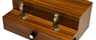
↑ Housing
For me, the body is simply incredible work. I can apply extraordinary patience and still it will turn out crooked and miserable. And in general, when it’s collected, it lies on the floor, works and sings - it opens up a terrible attack of laziness to do anything further.
I'm putting everything in its place. I wanted to make an illustration, but as always I was deceived with the sizes.
Covered with sheet plastic.
Air outlet at the top.
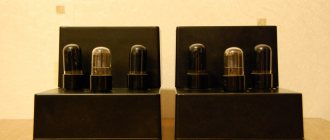
And finally assembled:
↑ Conclusion
I put it together and the amp started working right away, which is the greatest miracle! I liked the sound more than the sound of the 6P7S. Although there is practically no power reserve, my old 35AC pumps quite well. I especially liked the bottom - it’s dense, pleasant, and “non-straining.” I like the complete lack of background.
I hope someone will also find this use of impulses useful. I call them “lazy IIPs”. It is simple and inexpensive to assemble. Such a modified UPS with an additional transformer works for me in 3 amplifiers. Everything is stable, the flight is normal.