When making my amplifier, I firmly decided to make an 8-10 cell LED output power indicator for each channel (4 channels). There are plenty of schemes of such indicators, you just need to choose according to your parameters. At the moment, the choice of chips on which you can assemble an ULF output power indicator is very large, for example: KA2283, LB1412, LM3915, etc. What could be simpler than buying such a chip and assembling an indicator circuit) At one time I took a slightly different route...
Preface
To make output power indicators for my ULF, I chose a transistor circuit. You may ask: why not on microcircuits? — I’ll try to explain the pros and cons.
One of the advantages is that by assembling on transistors, you can debug the indicator circuit with maximum flexibility to the parameters you need, set the desired display range and smoothness of response as you like, the number of indication cells - at least a hundred, as long as you have enough patience to adjust them.
You can also use any supply voltage (within reason), it is very difficult to burn such a circuit, and if one cell malfunctions, you can quickly fix everything. Of the minuses, I would like to note that you will have to spend a lot of time adjusting this circuit to your tastes. Whether to do it on a microcircuit or transistors is up to you, based on your capabilities and needs. We assemble output power indicators using the most common and cheap KT315 transistors. I think every radio amateur has come across these miniature colored radio components at least once in his life; many have them lying around in packs of several hundred and idle.
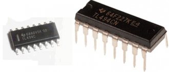
Rice. 1. Transistors KT315, KT361
The scale of my ULF will be logarithmic, based on the fact that the maximum output power will be about 100 Watts. If you make a linear one, then at 5 Watts nothing will even glow, or you will have to make a scale of 100 cells. For powerful ULFs, it is necessary that there be a logarithmic relationship between the output power of the amplifier and the number of luminous cells.
Redrawing peak level indicators
Next we suggest downloading the Holy_Signal top and bottom indicator. Its algorithm defines extremes as the maximum High or minimum Low over an interval of SignalGap length of candles to the left and to the right. Moreover, if the High (Low) of the current candle is the maximum (minimum) in the interval of the length of the SignalGap of candles to the left, then an arrow will be formed above (below) it, indicating the local extremum. But if during the next SignalGap candles another even higher maximum (smaller minimum) appears, then the arrow will be moved to it. Therefore, Holy_Signal is a redrawing indicator.
It is advisable to use it to build support and resistance levels that will pass through several successive minimums or maximums (Fig. 3).
The SignalGap numeric parameter specifies the interval within which the extremum will be searched. Thus, SignalGap determines the sensitivity of the Holy_Signal peak level indicator (the higher its value, the fewer extremes will be identified).
Schematic diagram
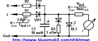
The circuit is outrageously simple and consists of identical cells, each of which is configured to indicate the desired voltage level at the ULF output. Here is a diagram for 5 indication cells:
Rice. 2. Circuit diagram of the ULF output power indicator using KT315 transistors and LEDs
Above is a circuit for 5 display cells; by cloning the cells you can get a circuit for 10 cells, which is exactly what I assembled for my ULF:
Rice. 3. Diagram of the ULF output power indicator for 10 cells (click to enlarge)
The ratings of the parts in this circuit are designed for a supply voltage of about 12 Volts, not counting the Rx resistors - which need to be selected. I’ll tell you how the circuit works, everything is very simple: the signal from the output of the low-frequency amplifier goes to the resistor Rin, after which we cut off a half-wave with diode D6 and then apply a constant voltage to the input of each cell. The indication cell is a threshold key device that lights up the LED when a certain level at the input is reached.
Capacitor C1 is needed to ensure that, even with a very large signal amplitude, the smooth switching off of the cells is maintained, and capacitor C2 delays the lighting of the last LED for a certain fraction of a second to indicate that the maximum signal level - peak - has been reached. The first LED indicates the beginning of the scale and is therefore constantly lit.
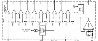
Brief description of LM3915
The LM3915 block diagram consists of ten identical operational amplifiers operating on the comparator principle. The direct inputs of the op-amp are connected through a chain of resistive dividers with different resistance values. Thanks to this, the LEDs in the load light up according to a logarithmic dependence. The inverse inputs receive an input signal, which is processed by a buffer op-amp (pin 5).
The internal structure of the IC includes a low-power integrated stabilizer connected to pins 3, 7, 8 and a device for setting the glow mode (pin 9). The supply voltage range is 3–25V. The reference voltage can be set in the range from 1.2 to 12V using external resistors. The entire scale corresponds to a signal level of 30 dB in 3 dB steps. The output current can be set from 1 to 30 mA.
Parts and installation
Now about the radio components: select capacitors C1 and C2 to your liking, I took each 22 μF at 63 V (I don’t recommend taking it for a lower voltage for ULF with an output of 100 Watt), the resistors are all MLT-0.25 or 0.125. All transistors are KT315, preferably with the letter B. LEDs are any that you can get.
Rice. 4. Printed circuit board for ULF output power indicator for 10 cells (click to enlarge)
Rice. 5. Location of components on the printed circuit board of the ULF output power indicator
I didn’t mark all the components on the printed circuit board because the cells are identical and you can figure out what to solder and where without much effort.
As a result of my labors, four miniature scarves were obtained:
Rice. 6. Ready-made 4 indication channels for ULF with a power of 100 Watts per channel.
↑ Century XXI, Attyny13
Simple and tasteful: we straighten and smooth the signal, then feed it to the ADC of the microcontroller.
We process it in software and, using the built-in PWM, output it to the load (resistor). Processing includes almost only natural logarithms (Attyny13 was created for such simple tasks, and so that the firmware could be baked in a hurry). And this is where the fun begins for me.
The natural logarithm function is available in the library of mathematical functions for Atmel controllers and is located in the file math.h. But it just doesn’t fit into this controller - there’s not enough memory. It’s not possible to solve the problem head-on, so we begin to wrinkle our forehead. The use of a more powerful controller was not considered - not interesting. There seems to be enough memory, and it’s convenient, and inexpensive, and the dimensions are not large. The first thing that came to mind was to replace this function with a similar one, but simpler. And give it shape by playing with the coefficients. Let us recall the graph of the inverse function. Not “screw it!”, but remember! If you move the lower right square upward relative to the X axis, and slightly move the coefficients back and forth, then it is quite possible to adjust it to the desired shape. Here it is, a formula that replaces the logarithm: Y=-8196/(X+28)+284. Can you imagine the horror of a controller doomed to calculate these values thousands of times per second at the whim of the owner, who wanted to remember his “golden childhood”?
But unpleasant emotions were also guaranteed for the owner of the controller. Short integer values were not enough to process the results, and the input and output had to be just that. For me, translating data presentation formats in controllers from one to another has always been difficult. The wrinkles on my forehead multiplied.
The second option was born
— calculate everything in advance, and the controller will simply select data from the array that corresponds to the input values and throw them out to the output. We prepare the values, set the array - compilation error. The array dimension is too large for this controller. But making several arrays and tinkering with them depending on the input value of the ADC is not kosher. Thoughts about Newton's binomial swarmed, but were rejected due to non-constructiveness.
Here a phrase from a lecturer in higher mathematics from a university came to mind: “Using a cubic spline approximation, you can describe any function.” Well, we don’t need a cubic one, but a linear spline will do just fine! Thus, I practiced a little in OO Calc, and wrote a system of equations that fairly accurately replicate the graph of a logarithmic function using line segments:
if (n>=141) x=2*n+2020; else if (n>=66) x=5*n+1600; else if (n>=38) x=9*n+1330; else if (n>=21) x=15*n+1110; else if (n>=5) x=40*n+600; else if (n>0) x=160*n+50; if (n==0) x=0; Everything is deliberately multiplied by 10 so that the discarded “tails” are smaller. I then divide it in the program before displaying it on indicators. And here are the graphs:
I am sure that such a solution will immediately come to mind for many of you and seem obvious. However, I am sure that this will be new to someone and will be useful in the future. At least as a tool in your arsenal it will not be superfluous to have.
Settings
First, let's adjust the brightness of the LEDs. We determine what resistor resistance we need to achieve the desired brightness of the LEDs. We connect a 1-6 kOhm variable resistor in series to the LED and supply this power circuit with the voltage from which the entire circuit will be powered; for me it’s 12V.
We twist the variable and achieve a confident and beautiful glow. We turn off everything and measure the resistance of the variable with a tester, here are the values for R19, R2, R4, R6, R8... This method is experimental, you can also look in the reference book for the maximum forward current of the LED and calculate the resistance using Ohm's law.
The longest and most important stage of setup is setting the indication thresholds for each cell! We will configure each cell by selecting the Rx resistance for it. Since I will have 4 such circuits of 10 cells each, we will first debug this circuit for one channel, and it will be very easy to configure others based on it, using the latter as a standard.
Instead of Rx in the first cell, we put a variable resistor of 68-33k in place and connect the structure to an amplifier (preferably to some stationary, factory one with its own scale), apply voltage to the circuit and turn on the music so that it can be heard, but at a low volume. Using a variable resistor, we achieve a beautiful wink of the LED, after that we turn off the power to the circuit and measure the resistance of the variable, solder a constant resistor Rx into the first cell instead.
Now we go to the last cell and do the same thing only by driving the amplifier to the maximum limit.
Attention!!! If you have very “friendly” neighbors, then you can not use speaker systems, but get by with a 4-8 Ohm resistor connected instead of the speaker system, although the pleasure of setting it up will not be the same))
Using a variable resistor, we achieve a confident glow of the LED in the last cell. All other cells, except the first and last (we have already configured them), you configure as you like, by eye, while marking the power value for each cell on the amplifier indicator. Setting up and calibrating the scale is up to you)
Having debugged the circuit for one channel (10 cells) and soldered the second one, you will also have to select resistors, since each transistor has its own gain. But you don’t need any amplifier anymore and the neighbors will get a small timeout - we simply solder the inputs of two circuits and supply voltage there, for example from a power supply, and select the Rx resistance to achieve symmetrical glow of the indicator cells.
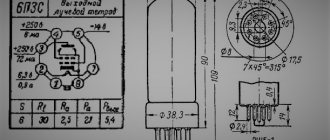
↑ Tradition of deep antiquity... K157DA1
A special microcircuit for this was released in the USSR - K157DA1
. The microcircuit has no analogues abroad. The connection diagram is simple, although according to the datasheet, bipolar power is required (inconvenient). But the microcircuit also works successfully on single-supply power. Moreover, the use of transistors instead of diodes in the circuit allows you to expand the range of displayed values up to 40 dB:
Various variations of this scheme are a dime a dozen on the Internet. Well, what can I say... It didn’t work out for me.
The first copy successfully burned due to improperly supplied power.
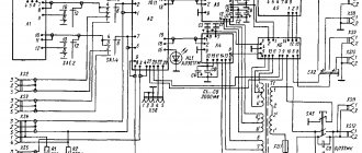
Within a month, I got two more things, but it was too late, I switched to another circuit (on LM324), kindly provided to me by AlexD
. Just for fun, I later turned on the board with DA1. I didn’t like it, there was no smooth movement. The modification of the circuit was carried out in close cooperation with Alexey, for which once again “danke shon”!
What is a current transformer
The basis of these indicators is a current transformer. A ring magnetic circuit with a winding is put on one of the network wires entering the apartment, forming a current transformer . In it, the network wire acts as the primary winding of the transformer, and the winding on the magnetic core is the secondary winding. When any load is turned on, current flows through the network wire and an alternating voltage appears on the secondary winding, the value of which can be used to judge the electrical appliances that are currently turned on. The higher this voltage, the greater the power consumption.