In the era of portable electronics, the issue of powering portable devices is becoming more and more pressing. Particularly difficult is the bipolar supply voltage required, for example, in a portable headphone amplifier. Today's development of electronics allows us to overcome this problem. Let's look at how to make bipolar power supply from unipolar one on the TPS65133 chip.
Bipolar power options for a portable device
Of course, for bipolar power supply in a portable device, you can use two batteries. But this will lead to additional difficulties with charging them, as well as imbalance of the arms as the batteries age.
A more advanced option to make bipolar power from unipolar is to use a dc-dc voltage inverter MAX660, MAX865 or any other. But there is a problem here too. When the battery is discharged, following the positive voltage, the negative voltage will also drop. Those. with a charged battery the power will be ±4.2, and with a discharged battery ±3 V or even less.
And here SEPIC converters come to the rescue. We will not delve into the theory of the transformation process - this is the topic of a separate article. For now, let's look at the unipolar to bipolar voltage converter on the TPS65133.
Speaker return current
As you know, the acoustic system is a reactive load. This means that it can return current to the amplifier. This current, flowing through the conductors, creates a potential difference, which can lead to positive feedback and, as a result, instability of the amplifier.
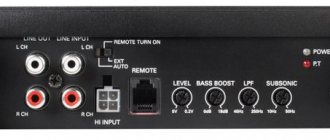
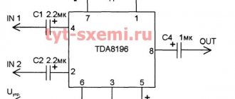
To avoid this, the speaker ground terminal should be connected to the common terminal of the power filter capacitors. Often the speaker terminal is connected to the common terminal of the microcircuit, as shown in the figure:
This connection closes the negative half-wave of the signal into a local loop, eliminating the filter capacitor that could reduce radiated interference and improve system stability.
The figure shows how the ground leakage current of one half-wave of the signal can cause unpleasant noise and distortion if the common wire of the speaker is connected to the output stage of the microcircuit:
Similarly, if on the amplifier board in the power circuits there are bypass capacitors (and they usually are) of a fairly large capacity of several hundred microfarads, then the charging current pulses will also create a potential difference on the common conductor. Therefore, we repeat once again, the best point for connecting the common wire of the speaker system is the common terminal of the power filter capacitors.
Bipolar power supply from unipolar one on the TPS65133 chip
The main advantage of this converter is that the output voltage is ±5V regardless of the input voltage, which can be from 2.9 to 5 volts (up to 6 volts can be supplied). Those. The microcircuit is designed for direct use with 3.6 volt batteries. But no one forbids powering it from USB or a power supply.
The conversion frequency here is 1.7 MHz. This is a great option for audio devices. At the same time, operation does not require the use of transformers, which are needed in most SEPIC converters. The conversion requires only inductance which, due to such a high frequency, is quite small.
The circuit of the unipolar to bipolar voltage converter on the TPS65133 is as follows:
It is advisable to install tantalum capacitors. It would also be a good idea to install additional 0.1 µF capacitors to filter out RF interference.
As for such a parameter as output current, everything is very good here. The output current can reach 250 mA per arm. The manufacturer claims that with an output current of 50 to 200 mA, the efficiency of the converter exceeds 90%, which is a very good indicator for use in portable equipment.
Dear user!
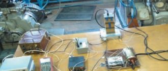
We assemble a simple bipolar laboratory power supply for the laboratory of a novice radio amateur. Good afternoon, dear radio amateurs! In this lesson of the Beginner Radio Amateur School, we will begin to create a radio amateur laboratory. For more or less high-quality execution of the intended design, a radio amateur needs a minimum set of instruments to configure and test the functionality of the circuit he is assembling. In addition to the multimeter tester, you must have: a laboratory power supply to check the functionality and configure the circuit, and so that for each circuit, before setting it up, do not assemble a separate power source; generator of rectangular, sawtooth, sinusoidal pulses - for setting up the circuit; frequency meter for measuring the frequency characteristics of the assembled circuit or its settings. These are the main devices. We'll start with a laboratory power supply.
A bipolar voltage stabilizer based on a unipolar DA1 microcircuit with a stabilization voltage of 5 V is made according to the circuit in Fig. 12th century
Fly in the ointment
Despite all the obvious advantages, the biggest disadvantage of this microcircuit is its housing. The microcircuit is produced only in a package designed for surface mounting, measuring 3x3 mm. The dimensions of the contacts are 0.6x0.2 mm, and the distance between them is 0.25 mm.
Making a board with such contacts at home is not the easiest task. You can make your life easier if you buy a ready-made module with a soldered chip and wiring.
In general, TPS65133 is not the only one. In the same series there are TPS65130 TPS65131, TPS65132, TPS65135….. However, either their characteristics are less interesting, or the case is even worse.
I would be very grateful to anyone who can suggest microcircuits with similar characteristics. I'm waiting for you in the comments
The material was prepared exclusively for the site
Using Op Amps
As is known, the current-voltage characteristic of diodes is nonlinear; by creating a single-phase precision (high-precision) full-wave rectifier on an op-amp chip, the error can be significantly reduced. In addition, it is possible to create a converter that allows you to stabilize the current on the load. An example diagram of such a device is shown below.
Circuit: a simple op-amp stabilizer
The figure shows a simple current stabilizer. The op amp used in it is a voltage controlled source. This implementation makes it possible to ensure that the current at the output of the converter does not depend on the voltage loss across the load Rн and the diode bridge D1-D4.
If voltage stabilization is required, the converter circuit can be slightly complicated by adding a zener diode to it. It is connected in parallel to the smoothing capacitance.
The more power, the worse.
Radio amateurs often try to make their amplifier as powerful as possible (like, it’s cooler), and audiophiles often equip their systems with amplifiers with a power many times greater than that required to sound an ordinary room to a normal volume level, citing the fact that this results in a larger dynamic range. Such amplifiers (high power) sometimes solve some problems, but create others.
The inductance of the power conductors is the main “weak link” of class AB power amplifiers. In such amplifiers, the output transistors are turned on and off alternately, respectively, half-waves of charging currents flow along the positive and negative power buses.
If these pulses enter the audio path through capacitive and inductive couplings, this results in a terrible blurry sound.
This happens if some sensitive track (conductor) passes next to the power bus. Bifilar laying of power wires effectively suppresses radiated interference due to mutual compensation of positive and negative half-waves.
On a printed circuit board, this method can be implemented if the power buses are placed one above the other on both sides of the board (a double-sided printed circuit board is required)
Grounding one side of the PCB works well in high frequency and low current designs. This is not suitable for power amplifiers because it is difficult to predict the flow of currents depending on the choice of ground points.
In modern tube amplifiers, the common bus is often made in the form of a piece of thick tinned wire. Many gurus preach star wiring with a single connection point. There are cases when amplifiers perform poorly with this approach. This is due to the large number of long wires that reduce the stability of the structure.
Typically, a good amplifier will have several ground points.
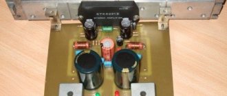
↑ Installation
To mount the module, I used homemade “stands” made of tinned wire with a diameter of 1 mm.
This ensured convenient installation and cooling of the modules.
The posts can get very hot when soldering and will not move like simple pins. The same design is convenient if you need to solder external wires to the board - good rigidity and contact. The board makes it easy to replace the DC-DC module if necessary. General view of the board with chokes from halves of some kind of ferrite core (inductance is not critical).
Despite the tiny dimensions of the DC-DC module, the overall dimensions of the board turned out to be comparable to an analog stabilizer board.